When a fleet operations manager in Hamburg encountered an evening depot-return surge, he added charge points so every van could plug in at once. The site’s demand peak climbed after 18:00, and the local connection became the bottleneck; charging had to be staggered. The reversal came from treating storage as part of the site’s power architecture—rather than assuming a larger charger alone would solve the problem.
Summary: Size battery storage from the charging schedule, site load, grid import limit, and recharge window—not capacity alone. For continuous EV loads, an 80% loading principle means a 40 A branch circuit supports a 32 A continuous load where the governing code uses that rule. Start with a measured demand profile, then model the kW peak to shave and kWh needed before selecting equipment or applying for a connection change.
An EV depot is an energy system with a time problem. EV charging station power requirements cover charger rating, building loads, protection, utility agreement, and control strategy. Storage can limit short-duration imports; it cannot create unlimited energy. The right size depends on both power (kW) and energy (kWh).
Site power architecture.
Start with the site load and charging-demand profile
A site load assessment begins with utility-meter or building-management intervals. Capture typical and busy days; chart base demand, vehicle arrival times, energy per vehicle, and available import capacity. Fifteen-minute data are often useful, although the tariff may use another interval.
For the Hamburg depot, assume an illustrative 250 kW import limit, a 70 kW building load at 18:00, and a managed charging request that reaches 300 kW for two hours. The excess above the limit is 120 kW. A battery that delivers 120 kW for two hours needs at least 240 kWh of usable discharge energy before allowing for conversion losses, reserve margin, battery operating limits, and aging. The calculation is illustrative; an EPC should validate it against metering data and the utility’s demand-measurement method.
Size kW, kWh, and charging speed together
Power determines how quickly storage can support chargers; energy determines how long it can do so. Battery sizing therefore has two linked checks: required discharge power in kW, and usable energy in kWh across the peak period. A system designed only for kWh may have insufficient inverter output; one designed only for kW may exhaust too early. Confirm the storage system’s permitted state-of-charge window and output at the expected ambient conditions instead of comparing headline capacities.
Voltage and current set the electrical side of the calculation. As a simplified example, a three-phase AC load is approximately √3 × line voltage × current × power factor. A 400 V, three-phase, 16 A service is roughly 11 kW at unity power factor; actual design must account for the applicable equipment rating and installation rules. An AC charger is often appropriate where dwell time is long, whereas higher-output DC equipment changes both the peak-load and interconnection conversation.
Protect circuits and choose the right supply architecture
Every charger needs a dedicated circuit sized for its continuous duty, conductors, protective device, disconnecting means, earthing arrangement, and local code requirements. In jurisdictions that apply an 80% continuous-load rule, a 32 A continuous EV charging load calls for a 40 A circuit rather than a 32 A breaker. That rule does not replace a design review: conductor ampacity, termination temperature ratings, installation method, voltage drop, and local regulations can change the result.
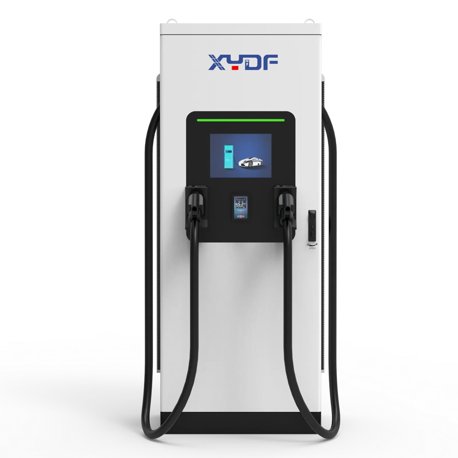
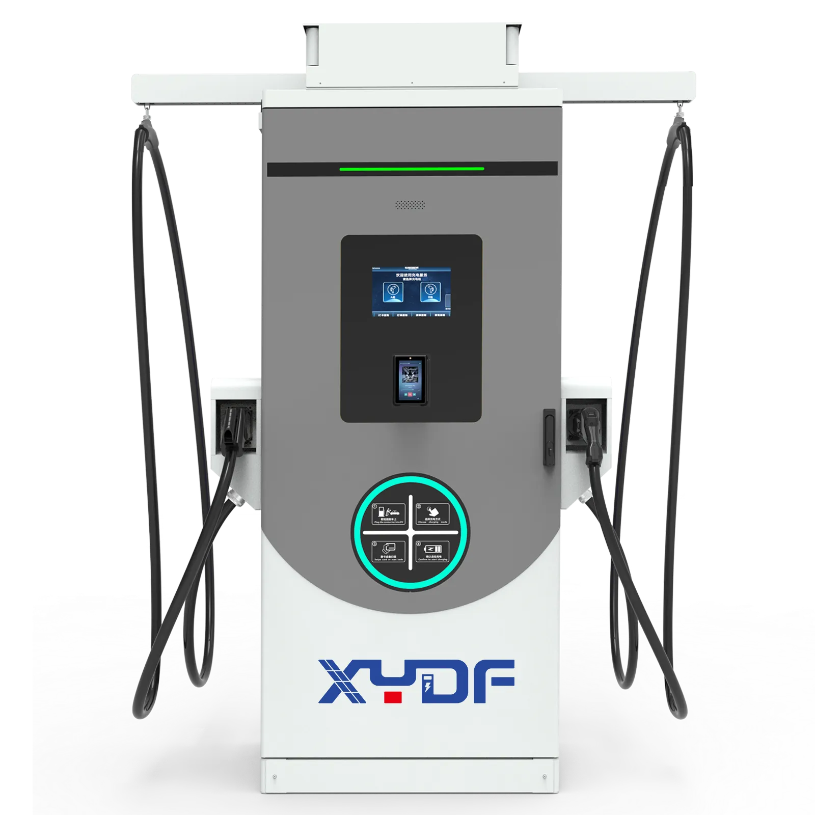
Single-phase service can suit modest AC charging where vehicles dwell overnight and available capacity is limited. Three-phase supply generally makes higher-power AC charging and balanced commercial distribution more practical; it also changes switchgear, cable, and utility requirements. For faster turnover, explore the operating implications of a 350 kW DC fast charger before setting a power target—vehicle acceptance rate and shared-power architecture may matter as much as the dispenser nameplate.
Application
Typical design priority
Storage role
Employee or destination parking
Moderate power and long dwell time
Limit occasional peaks.
Fleet depot
Departure certainty and synchronized returns
Cover concentrated evening demand and protect the import cap.
Public rapid charging
High throughput and network capacity
Bridge short peaks while interconnection is expanded.
Remote or temporary operation
Mobility and defined duty cycle
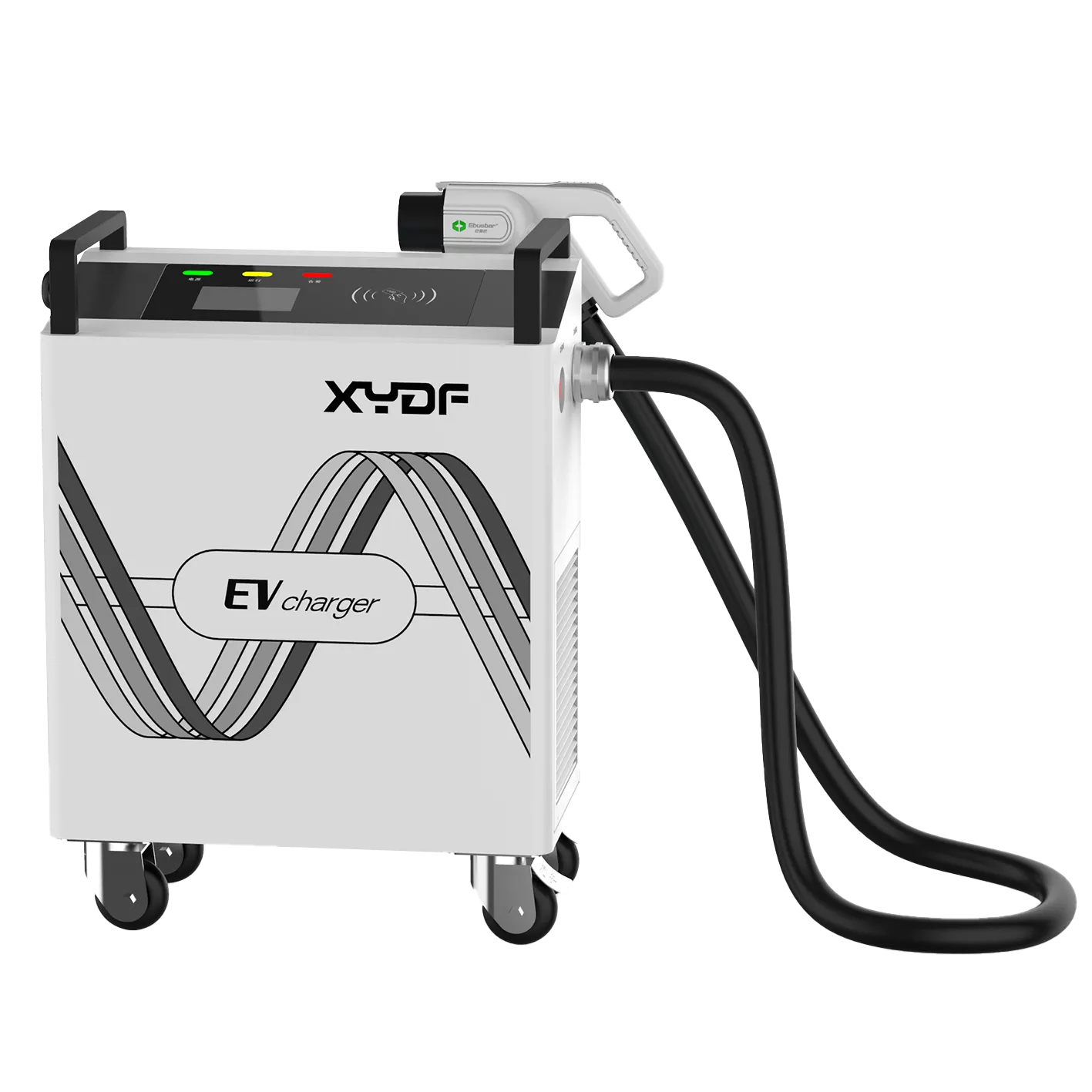
Assess a portable power station for EV charging against energy use and recharge access.
Plan the grid connection and future expansion from day one
Request the interconnection study early. The utility may specify transformer capacity, protection settings, meter configuration, export limits, or studies for a larger ev power station. Treat the utility agreement as a design input, not final paperwork. In Europe, connection and installation obligations remain dependent on the country, distribution network operator, and site.
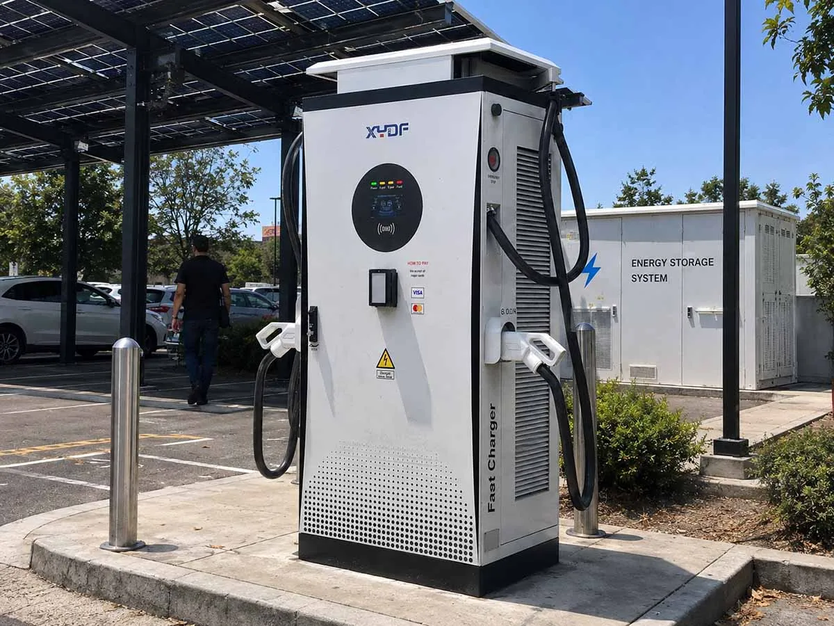
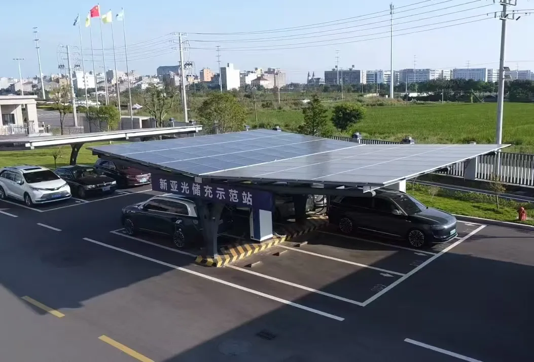
Reserve physical and electrical headroom for switchgear, conduits, communications, future battery racks, and transformer capacity. A solar power EV charging station also needs a realistic generation profile: Hamburg’s evening fleet-return peak may come after solar production falls. Storage may need to charge earlier from solar, the grid, or both. See solar and battery charging-station design for the system-level questions.
Standards, procurement, and a practical selection sequence
IEC 61851 addresses conductive EV charging systems, while IEC 60364-7-722 addresses low-voltage installations supplying EVs; neither proves a site is compliant or every product is certified. Confirm grid rules and equipment approvals for the destination market. Unsupported claims can delay commissioning and disrupt EPC handover.
Collect meter intervals, utility limits, fleet routes, and minimum departure state of charge.
Model normal, busy-day, and expansion charging cases with managed charging enabled.
Set battery kW from the peak above the import limit and usable kWh from the peak duration, then include technical reserve.
Have a qualified designer verify protection, earthing, cable sizing, and local interconnection requirements.
Specify monitoring data, service responsibilities, and expansion interfaces before procurement.
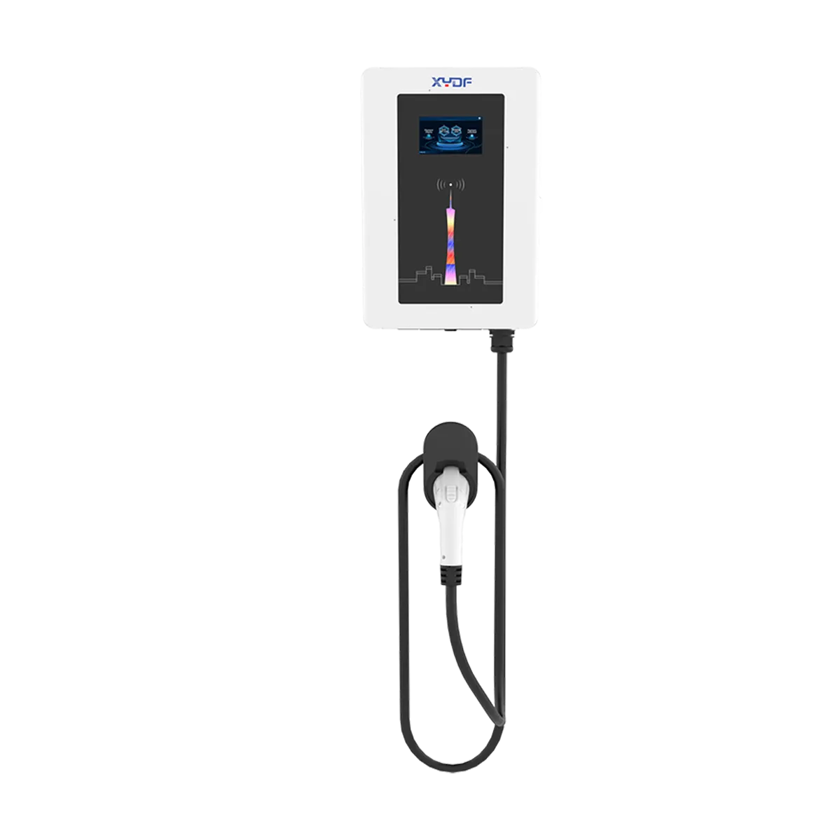
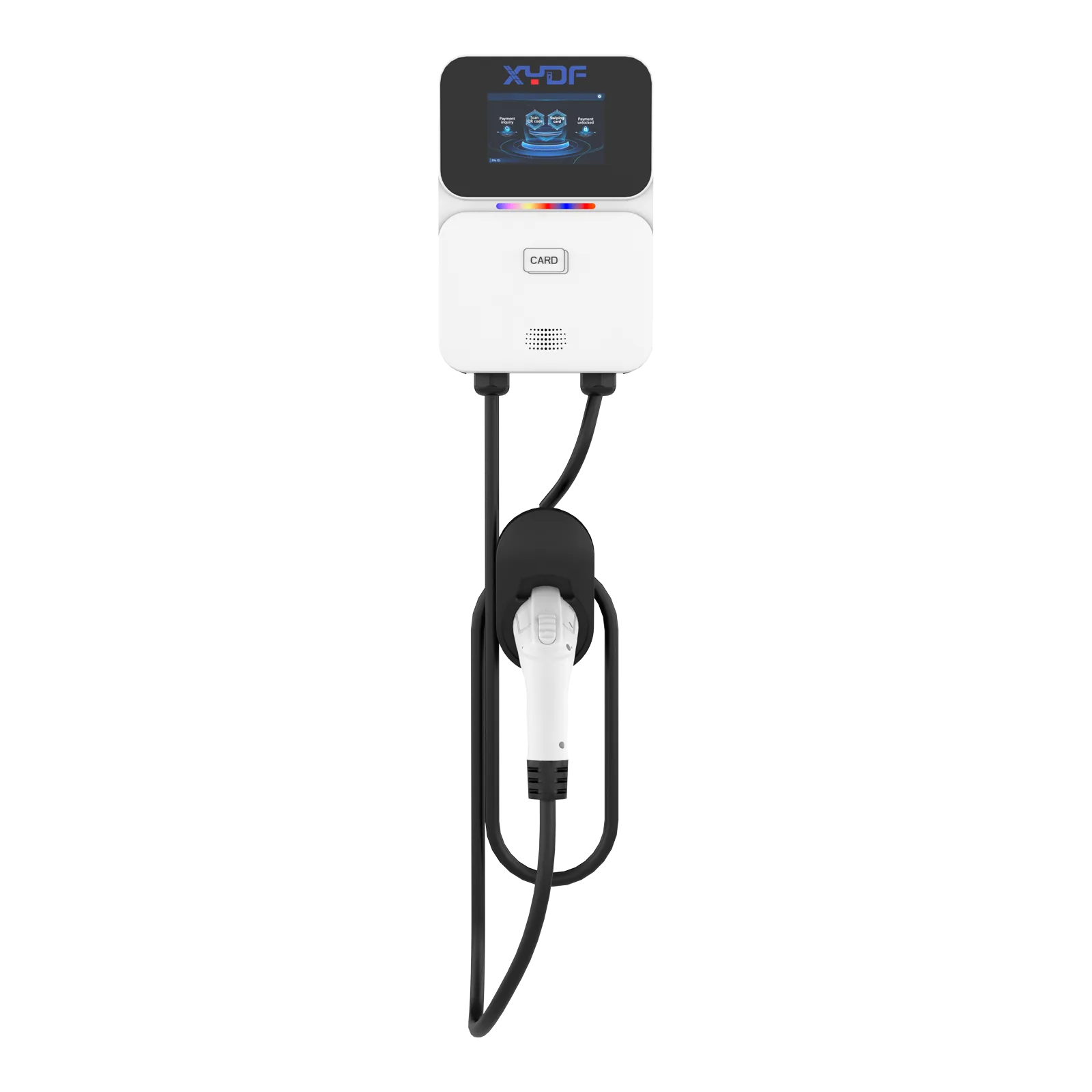
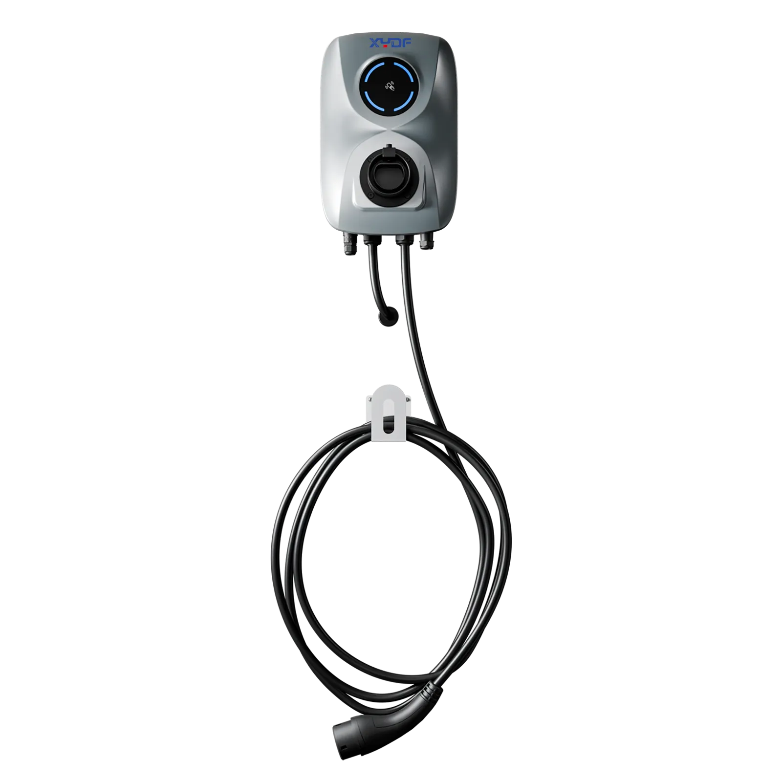
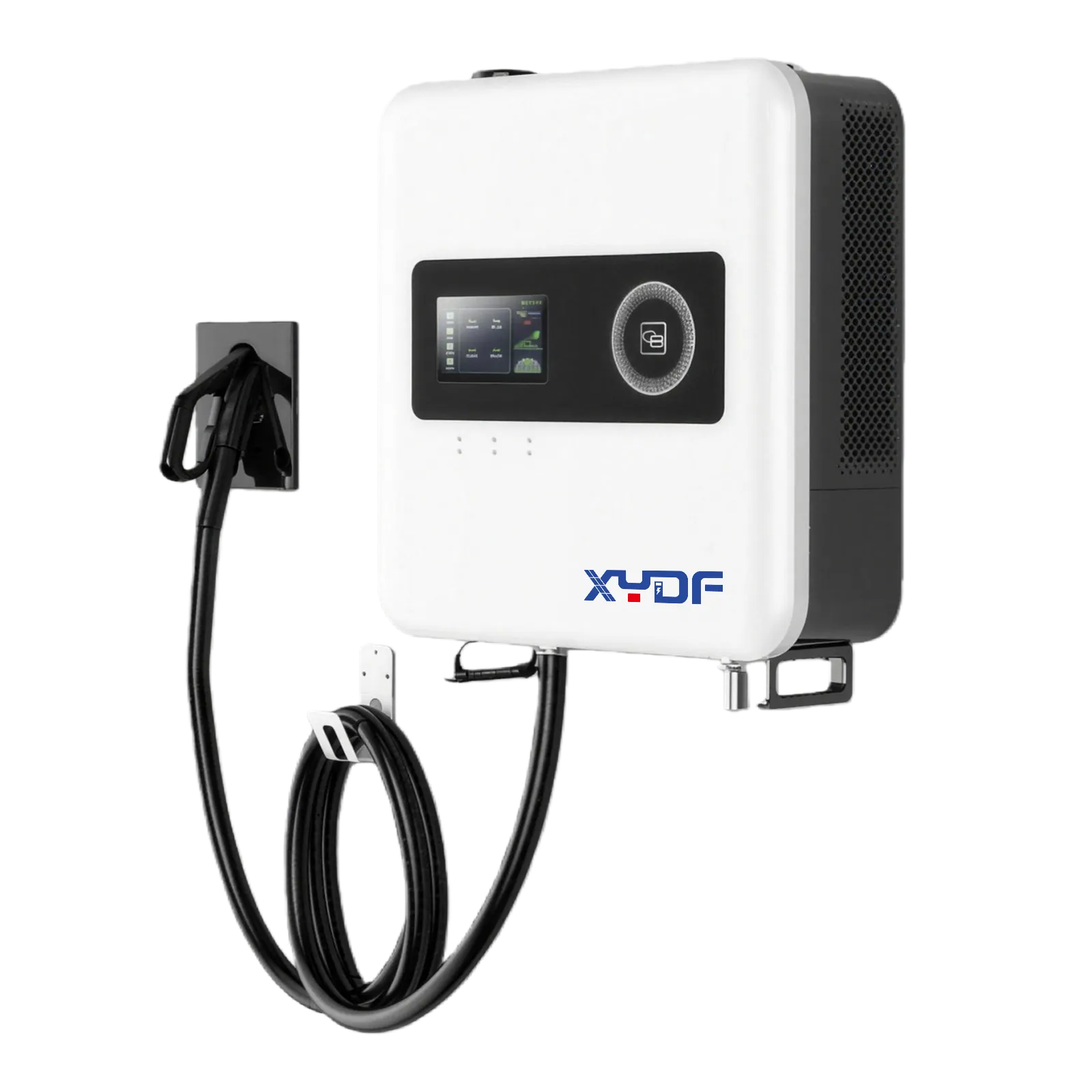
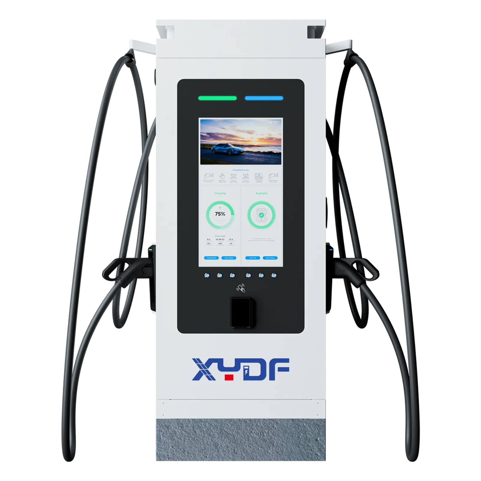
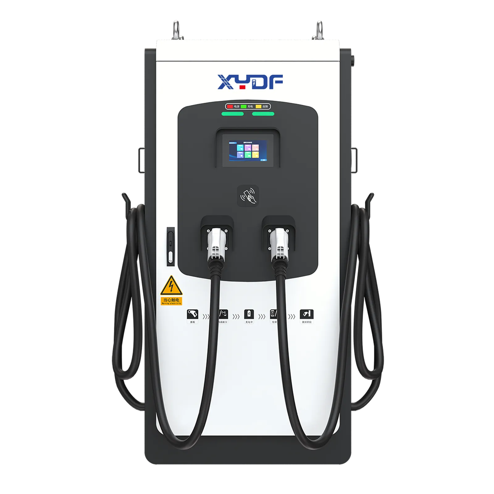
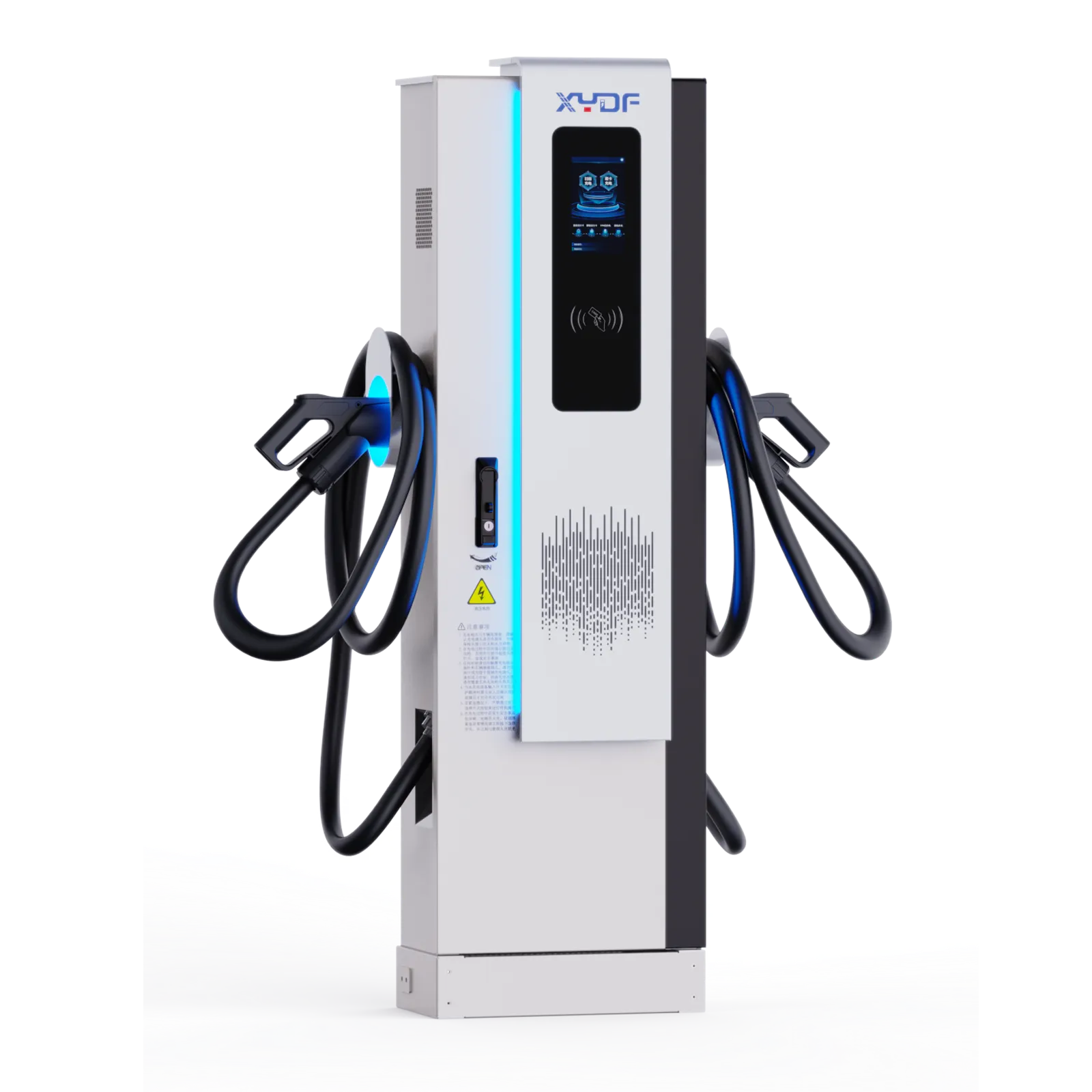
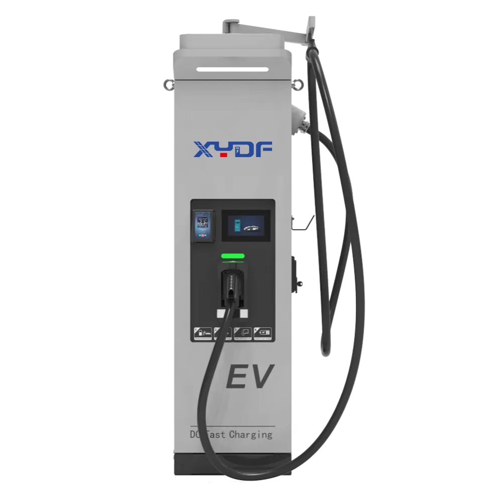
For buyers comparing configurable hardware and site-support documentation, XYDF can be a useful sourcing conversation after the load model is complete. Review the EV power charging station range with the actual utility cap, charging timetable, and required interfaces in hand; for high-throughput layouts, also evaluate a DC fast charger configuration against the site’s shared-power plan. Learn more about XYDF’s approach before setting supplier documentation requirements.
FAQ
What power is needed for an EV charger?
It depends on dwell time, energy needed by departure, AC onboard capability, and simultaneous vehicles. Divide required energy by the available window, then check that combined kW fits the import capacity or managed-storage strategy.
What are the electrical requirements for an EV charger?
They normally include a dedicated circuit, correctly rated conductors and breaker, suitable isolation and earthing, plus local installation and utility rules. Supply type, rating, installation method, and destination market determine the final design.
Can I use a 40 amp breaker for an EV charger?
Where the governing code applies the 80% continuous-load rule, a 40 A breaker can supply up to 32 A continuous charging. Verify the charger’s specified circuit, conductor sizing, local code, and panel capacity before installation.
Does an 11 kW charger need three-phase power?
In common European configurations, 11 kW AC charging typically uses three-phase supply, such as 400 V at 16 A per phase. Confirm vehicle compatibility and installation design rather than relying on a nominal label.
The best battery-storage design turns a fixed grid limit into a managed operating plan. When your team is ready to compare charger configurations with the measured load profile, contact XYDF through its EV charging product range to start a project discussion.
 Xinya Dongfang Electricity Technology Co., Ltd.