 شركة شينيا دونغفانغ لتكنولوجيا الكهرباء المحدودة.


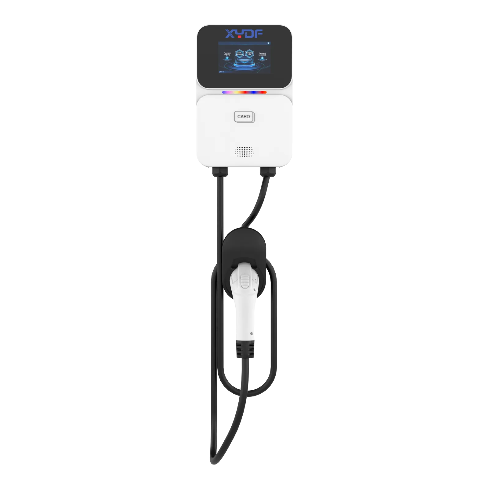
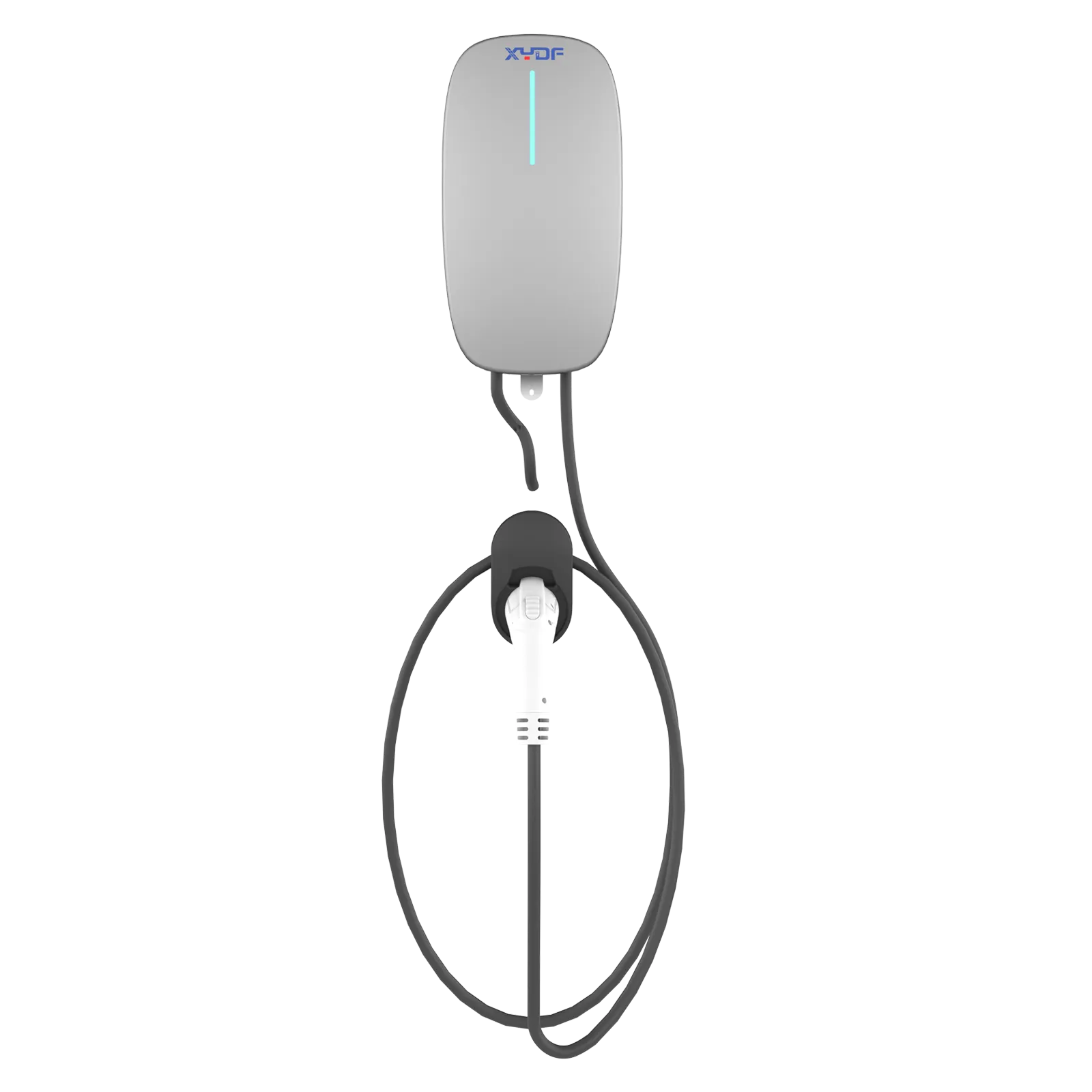
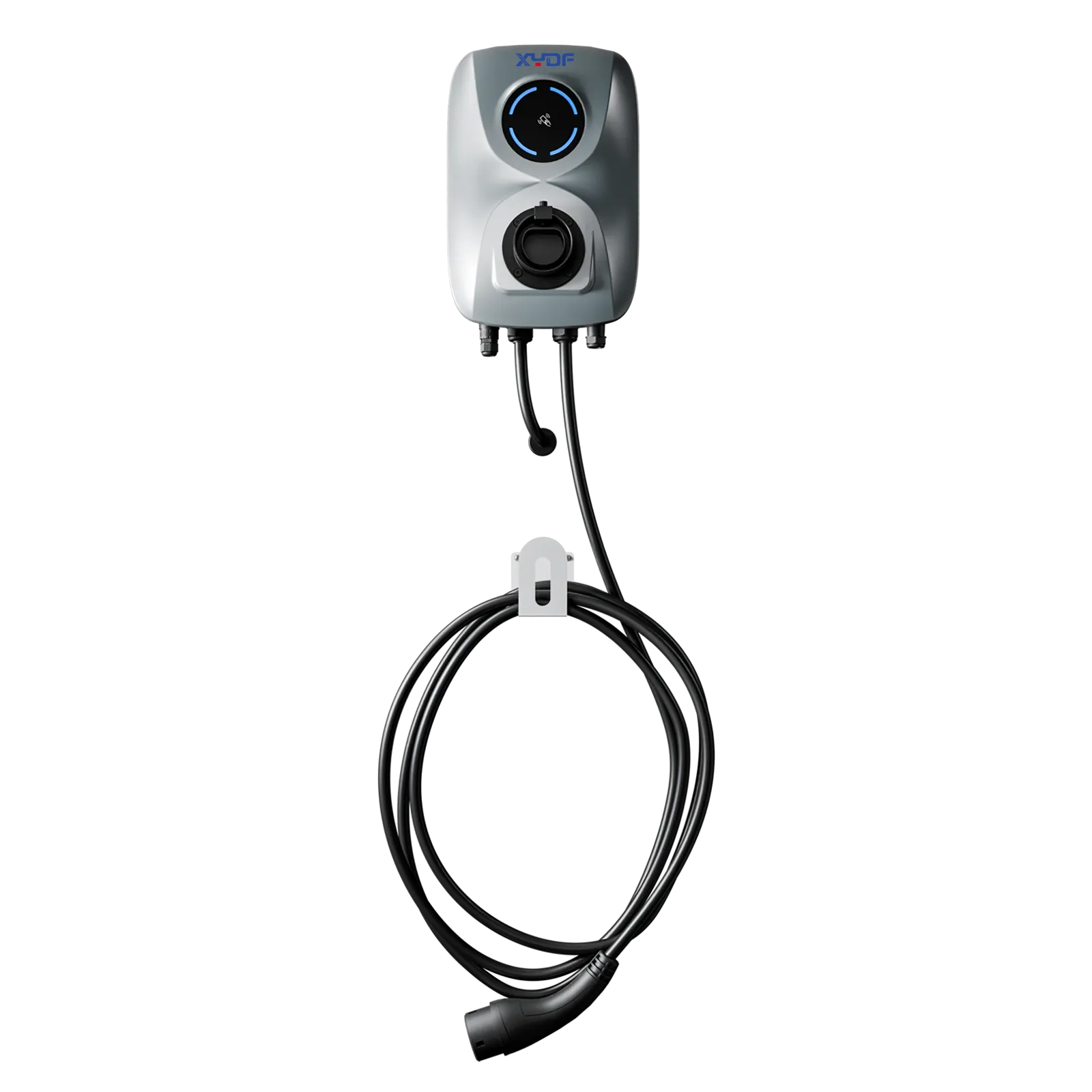

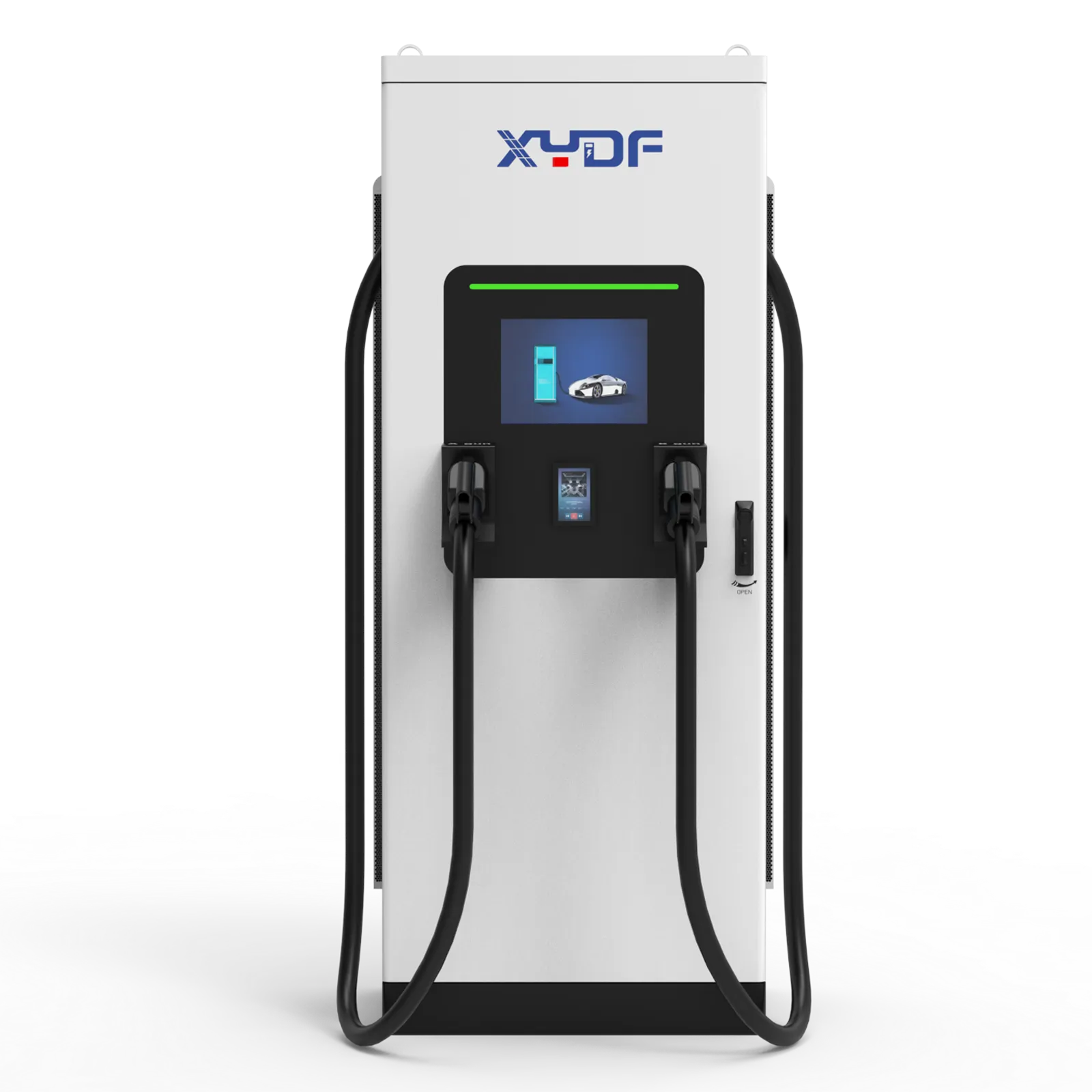
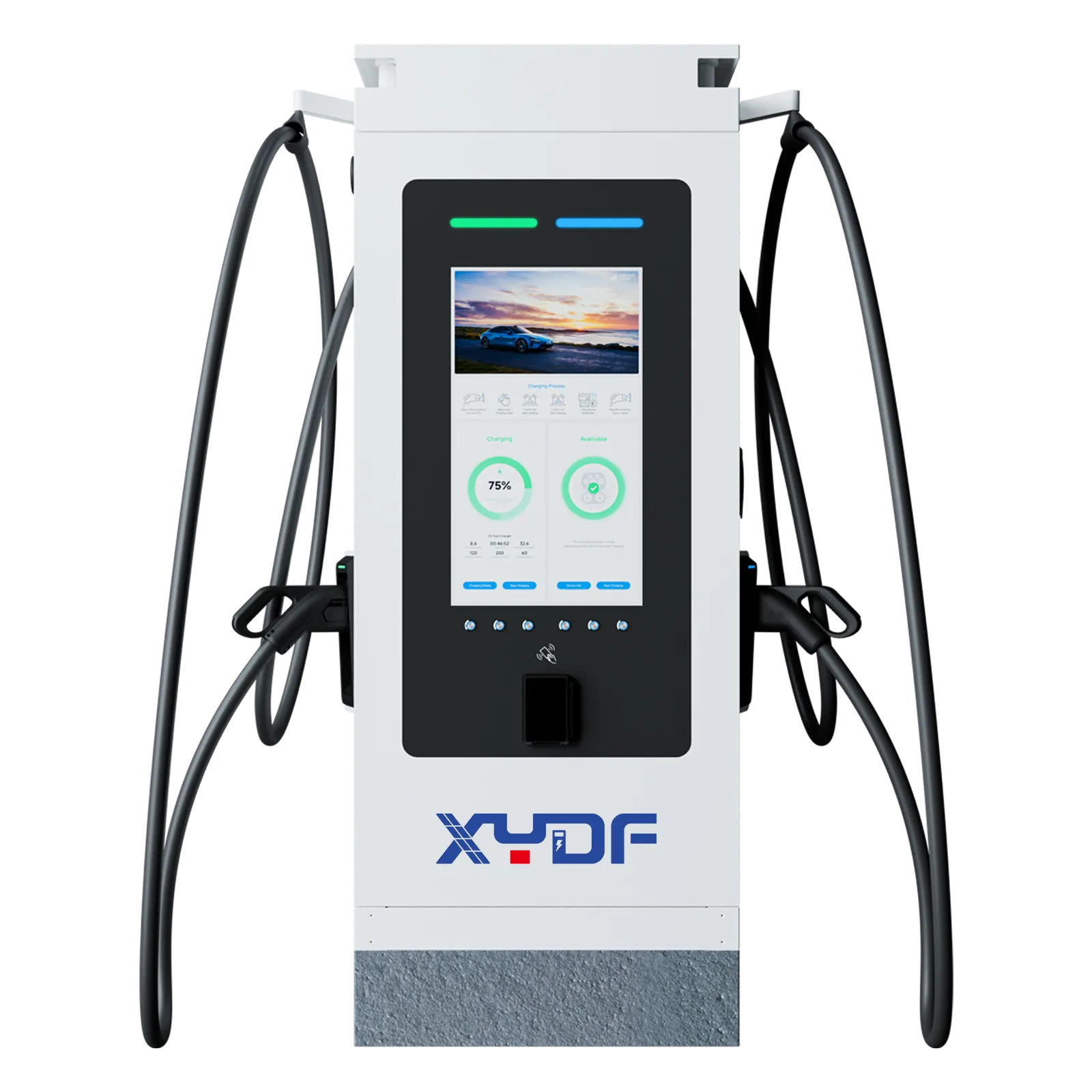
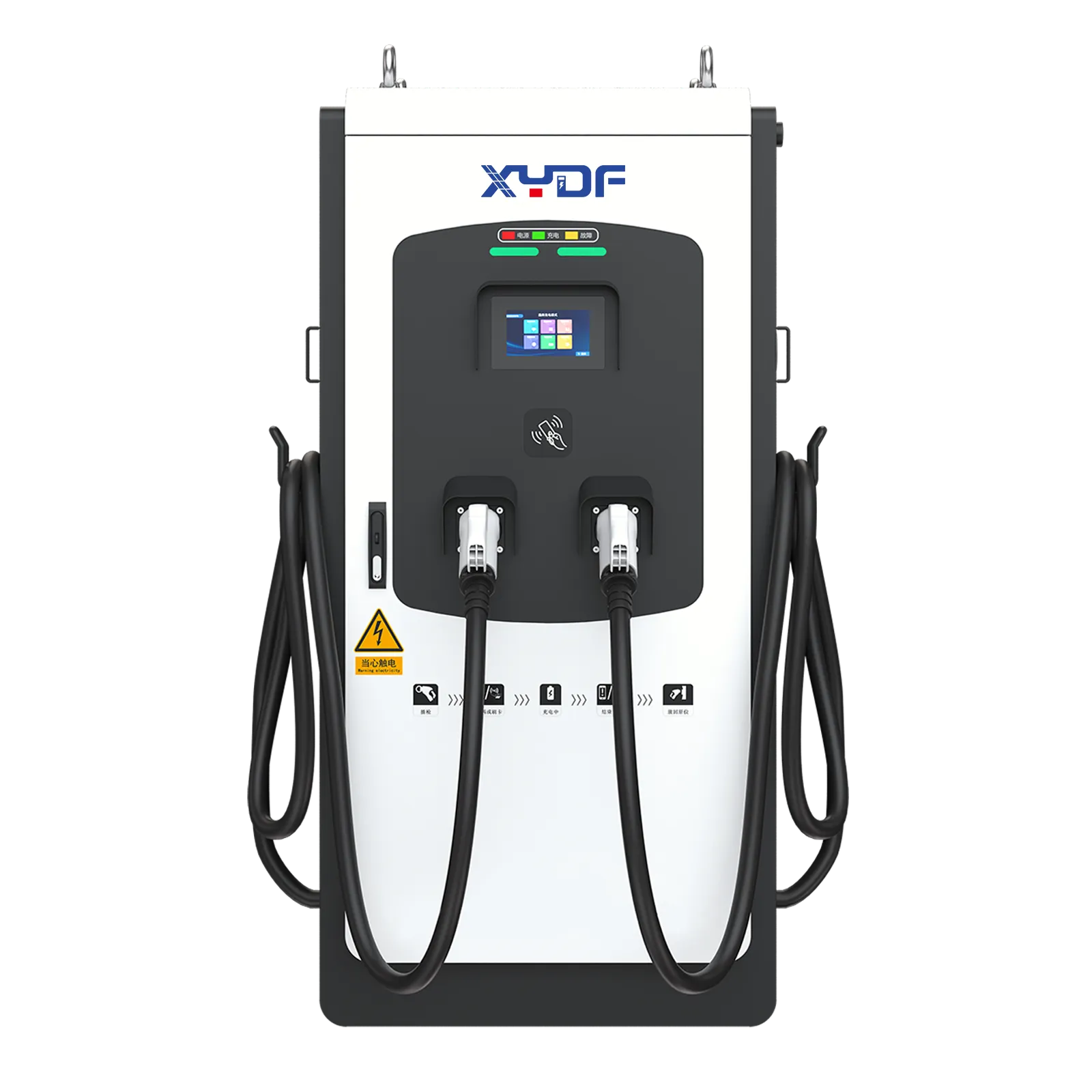
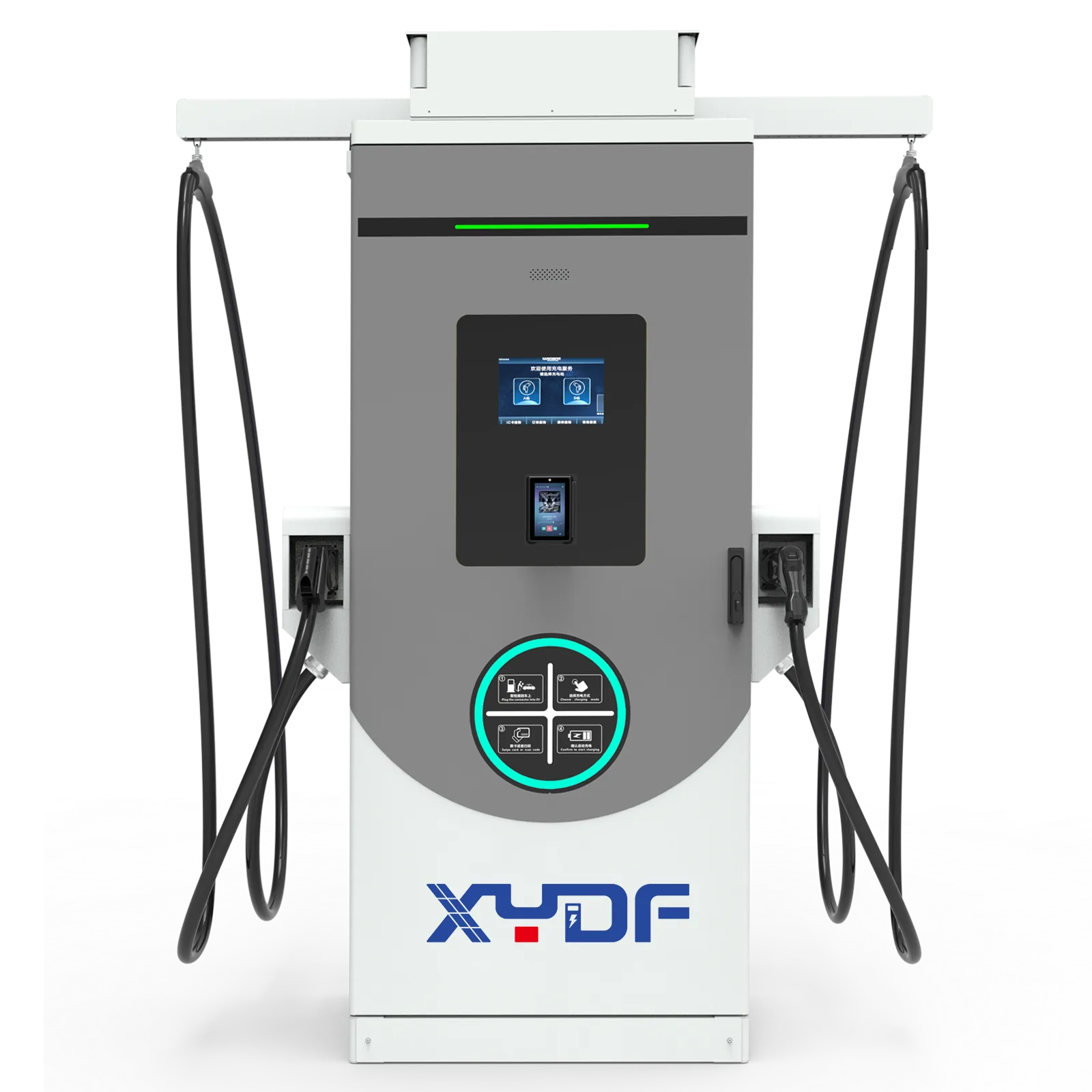
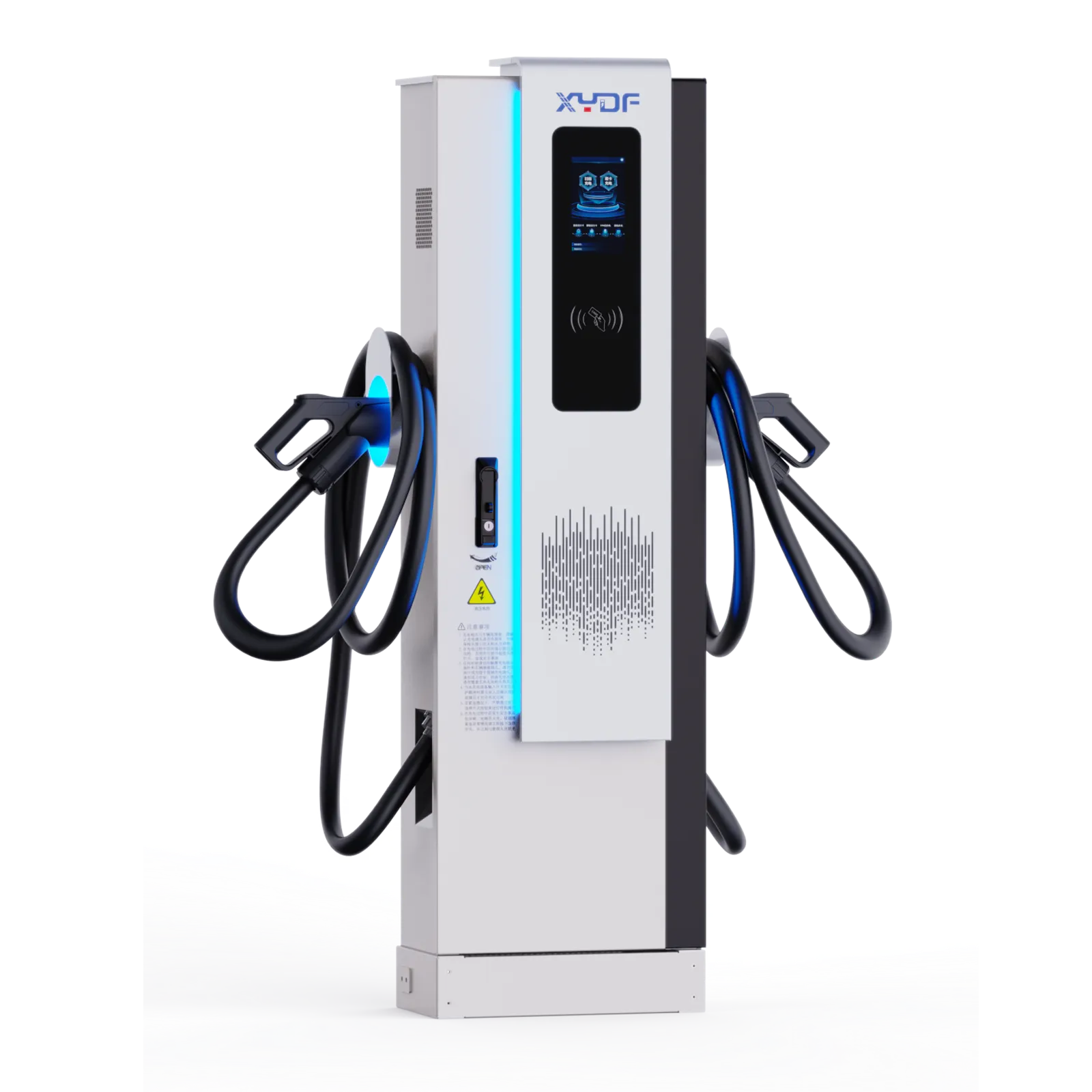
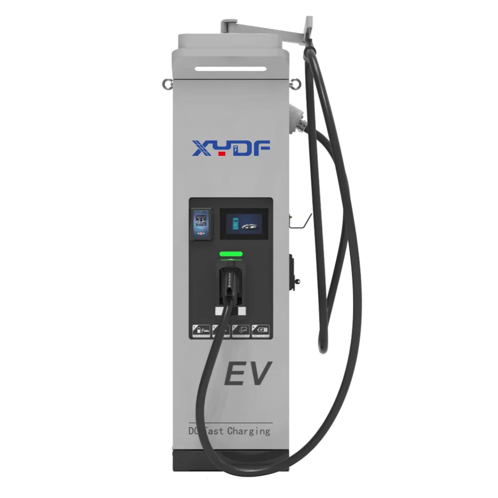
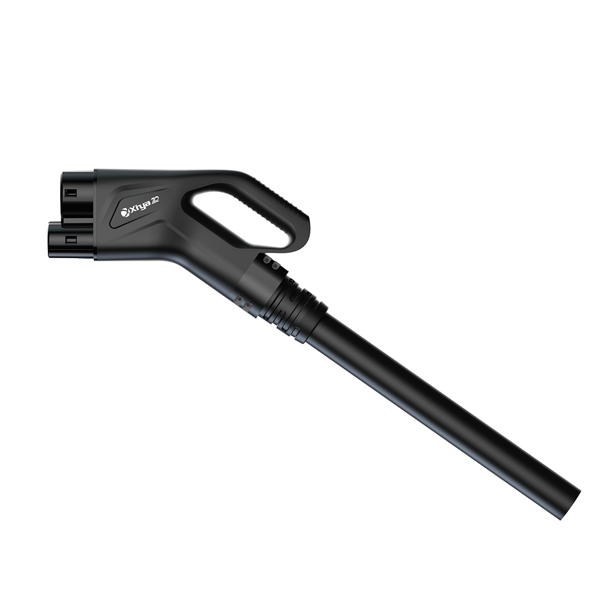
Ride-hailing and taxi charging is a turnaround-time problem: vehicles arrive with uneven battery levels, demand rises in waves and every minute spent waiting affects dispatch capacity. A site can have enough connectors yet still create a queue if the layout, power allocation, access rules and driver workflow are not matched to arrival and departure patterns. This guide explains how to model dwell time, queue behaviour, charging priority, payment or fleet credentials, and service recovery so a fleet EV charging system is evaluated as an operating process rather than a simple equipment count.
Effective شحن سيارات فليت EV begins with the minutes a vehicle can be off route, not with a nominal charger total. A practical depot plan measures the usable charge delivered during each shift break, models peak simultaneous arrivals, and sets dispatch rules before selecting hardware. IEC 61851-23 addresses DC EV supply equipment requirements, while the U.S. NEVI rule’s 150 kW minimum applies to a particular public-funding programme—not every taxi depot. For a fleet, the recommended action is to validate a 15-, 30-, or 45-minute turnaround target with real vehicle charge curves, connection time, and site power limits.
Taxi and ride-hailing vehicles concentrate energy demand into predictable yet sharp operating windows: handover, meal breaks, airport staging, and the period before an evening peak. A charger that works technically can still produce missed trips when the arrival pattern, vehicle battery acceptance, and driver behaviour were left outside the specification. The goal is therefore to make charging capacity available at the moment dispatch needs it.
Start with turnaround time, not nameplate power

Turnaround time is the full interval from a vehicle entering the depot to being dispatch-ready again. It includes bay access, connector handling, authorisation, charging, any repositioning, and a release check. A 150 kW cabinet does not put 150 kW into every vehicle: battery state of charge, temperature, voltage range, shared-power logic, and the vehicle’s own charging curve all influence delivered energy.
Specify an acceptance test that records meter energy and elapsed time for representative vehicles at agreed arrival states—for example, 20% to 80% state of charge—and repeats it during simultaneous use. IEC 61851-23 covers requirements for DC EV supply equipment, and IEC 61851-24 covers digital communication control between DC equipment and the vehicle; neither document is a blanket promise that every vehicle will sustain a charger’s rated output. This distinction protects fleet planners from sizing a fast charging station on a peak figure alone.
An illustrative turnaround calculation
Assume ten taxis need 36 kWh each during a 45-minute dispatch window. Their required energy is 360 kWh. If observed delivered power averages 90 kW after tapering and operating losses, one occupied connector supplies about 67.5 kWh in 45 minutes. That suggests more than five concurrently usable connector-equivalents before allowing for arrival bunching, blocked bays, or reserve. These figures are illustrative; fleet telematics and vehicle-specific charge curves must replace them in procurement.
Set taxi charger-to-vehicle ratios from peak arrivals
A fleet-wide ratio such as one connector per ten vehicles can be a starting indicator, but it cannot be the final answer for high-mileage taxis. The relevant ratio is connectors available during the busiest charging window divided by vehicles that must leave within that same window. A depot with staggered shifts may operate reliably at a lower overall ratio than a fleet whose drivers all return at changeover.
An evidence-led charging model treats that peak window as the sizing case and makes its service level explicit in the procurement brief.
Build an arrival histogram from at least several representative operating weeks, separating airport, urban, and reserve vehicles. Then run a simple discrete-event queue model with actual dwell time distributions rather than average dwell time alone. Track the 90th or 95th percentile wait, missed departure risk, and connector utilisation; high utilisation can look efficient while leaving no recovery capacity for a late vehicle.
| Planning input | What to measure | لماذا يتغير التصميم |
|---|---|---|
| Peak arrivals | Vehicles arriving per 15-minute interval | Determines simultaneous connector demand and queue exposure. |
| Usable break | Gate-in to dispatch-ready minutes | Sets the energy that must be delivered per vehicle. |
| قبول المركبة | Logged kW by state of charge and temperature | Prevents oversizing around cabinet nameplate ratings. |
| Operational buffer | Late arrivals, inaccessible bays, maintenance reserve | Protects service levels during imperfect operations. |
Before adding DC capacity, build a peak-window evidence set: arrival counts by 15-minute interval, usable bay time, connection time, energy required per route, vehicle charge curves, queue length, and missed-departure events. This makes the commercial question answerable: how much usable energy must the site deliver during the busiest window, and how much recovery capacity is needed when a bay is occupied or a vehicle arrives late?
Choose DC fast-charge power for the vehicle mix and grid
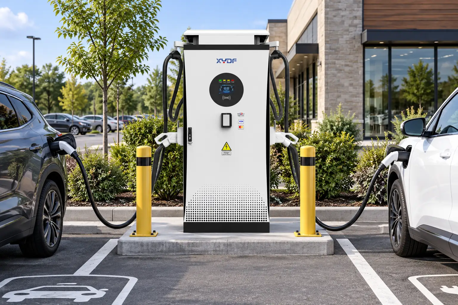
A بطارية شحن سريعة dc is most valuable where a vehicle’s available break is shorter than the energy it can recover through slower charging. For a mixed taxi fleet, a modular or shared-power layout may match diverse vehicle limits better than assigning every bay the highest nominal output. Confirm connector type, voltage range, simultaneous output behaviour, payment or access logic, and future vehicle compatibility in the request for quotation.
Electrical design also needs diversity and demand controls. Transformer capacity, feeder rating, switchgear duty, cable routing, ventilation where relevant, and utility tariff intervals can constrain the project before charger count does. A site acceptance test should verify protection functions and load-management response under the agreed number of simultaneous sessions; local electrical codes and the authority having jurisdiction determine the installation requirements.
| Operating pattern | Useful charging approach | Primary trade-off |
|---|---|---|
| Brief, high-priority return window | شاحن سريع التيار المستمر التجاري capacity matched to measured vehicle acceptance | Higher site demand may require utility and load-management work. |
| Longer overnight or layover dwell | ev fast charger bays supplemented by managed AC charging where dwell permits | Requires disciplined parking and departure scheduling. |
| Mixed route and reserve fleet | Priority DC bays plus scheduled lower-power charging | Control rules must keep DC bays free for urgent vehicles. |
Manage queues and smart schedules as one operating process
Queue management is not a sign that the chargers are inadequate; it is how a limited, time-sensitive resource stays aligned with dispatch. Assign drivers a target arrival state and a maximum target state of charge for a mid-shift stop, reserve priority bays for vehicles with imminent jobs, and alert an operator when waits exceed the agreed service threshold. A simple rule—charge only to the energy needed for the next route plus reserve—often improves bay turnover because charging commonly tapers at higher states of charge.
Use charger data, telematics, and dispatch records to review three measures weekly: median and tail wait time, kWh per occupied bay-hour, and late departures attributed to energy availability. Open Charge Point Protocol (OCPP) 2.0.1 is a communications protocol that can support operational data exchange where the chosen systems implement it; it is not, by itself, proof that a charger will interoperate with every back-office or vehicle.
Smart charging schedules allocate site power across vehicles according to departure time, required energy, tariff period, and grid limits. They should not blindly defer every session to the cheapest interval: a taxi that must serve a morning shift has a higher operational priority than a vehicle held in reserve. Start by establishing a minimum departure state of charge by route class, then let the control system fill remaining energy in lower-cost periods.
Before installation, a fleet ev charging policy should also name who can override a schedule and how that decision is recorded for later review.
For fleet ev charging, include a fall-back mode for communication loss, rules for charge-session interruption, and an operator override for late vehicles. Compare the projected demand profile with utility tariffs and site limits before promising savings. The business case should count not only electricity cost, but also lost trip revenue, driver time, electrical upgrades, maintenance access, and the value of avoiding an additional queue-prone bay.
Standards, compliance, and evidence to request
Standards must be matched to the market and the installed system. IEC 61851-1 addresses general conductive charging-system requirements; IEC 61851-23 addresses DC EV supply equipment; and IEC 61851-24 addresses digital communication control for DC charging. ISO 15118 concerns vehicle-to-grid communication interfaces and features such as Plug & Charge where supported by the full ecosystem. These are technical standards with defined scopes; a buyer should ask which edition, test evidence, and destination-market conformity route applies instead of treating a standards citation as a universal product certification.
For U.S. federally funded public charging covered by the National Electric Vehicle Infrastructure (NEVI) standards, requirements include at least four network-connected DC fast-charge ports per station and a 150 kW minimum per port, subject to the rule’s detailed conditions. Those requirements should not be copied uncritically into a private taxi depot or another country. Unsupported claims about compliance, power, uptime, or interoperability can create contract, safety, and tender risk.
- Convert dispatch commitments into a departure-time service level, including the maximum acceptable queue at each peak.
- Provide suppliers with vehicle models, battery capacities, connector requirements, observed charge curves, and a staged fleet-growth forecast.
- Require an illustrative load study covering simultaneous charging, demand caps, fail-safe behaviour, and the metering point used for acceptance.
- Plan bay geometry, cable reach, vehicle circulation, protection, drainage, maintenance clearance, and accessibility with the local designer and authority.
- Commission with representative vehicles and retain the timed-session results as the baseline for operations.
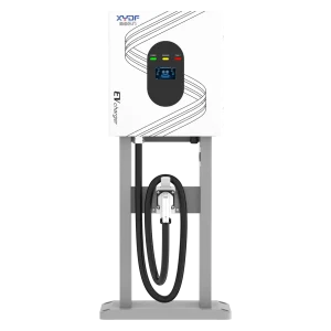
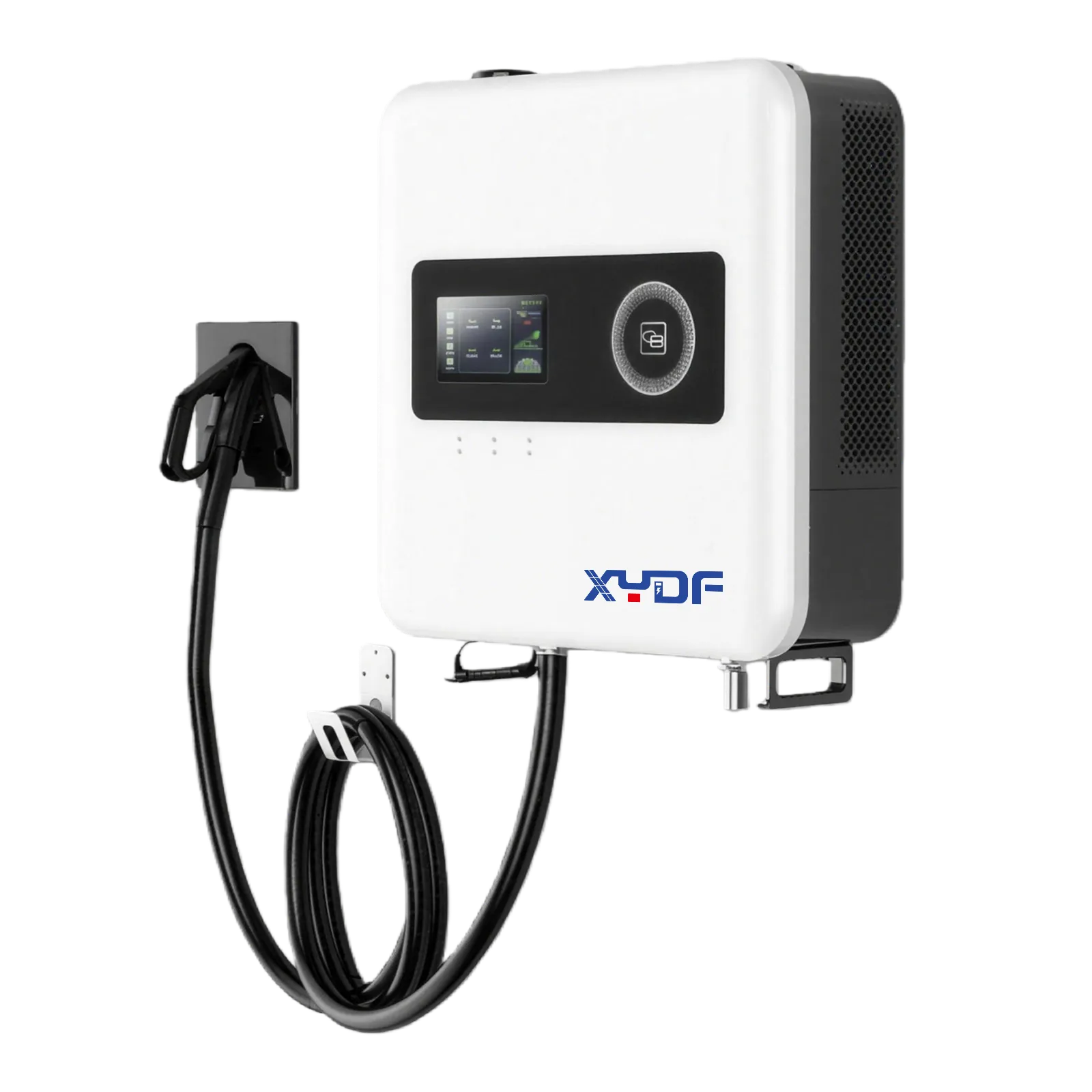
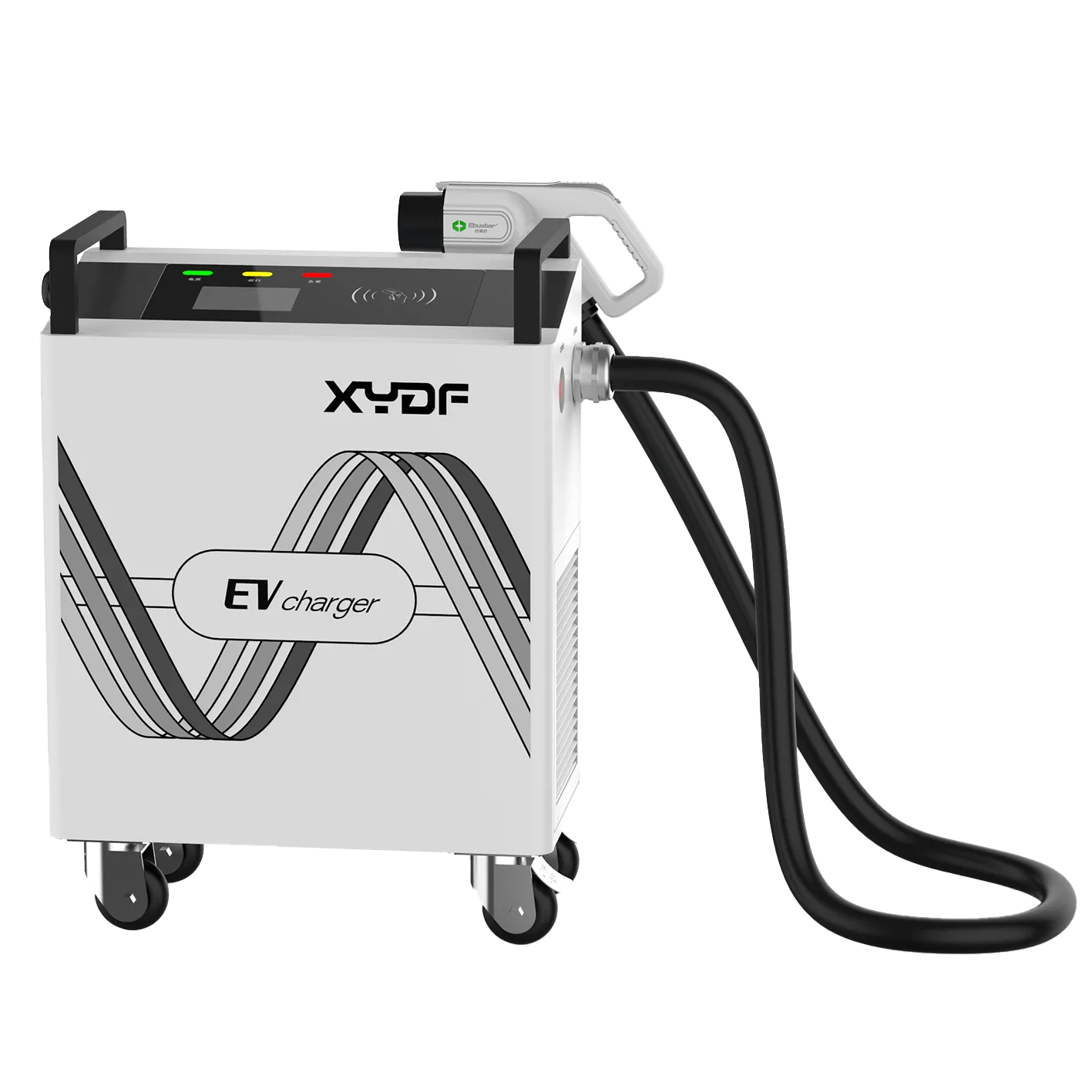
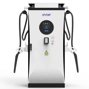
XYDF can be considered during the equipment-sourcing stage where a buyer needs to compare configurable charging hardware, documentation, and a defined commissioning scope. The useful question is not which catalogue unit has the largest number, but which system can meet the fleet’s measured departure promise without creating a new grid or queue constraint.

الأسئلة الشائعة
How fast should taxis charge between shifts?
They should charge fast enough to add the energy required for the next duty period within the usable break, with a dispatch reserve. Test representative vehicles over the expected arrival state-of-charge range; the charger’s rating alone is not a reliable timing guarantee.
Is DC fast charging necessary for ride-hailing fleets?
It is usually necessary when high-mileage vehicles have short dwell times and must return to service quickly. Fleets with dependable overnight dwell may use managed AC charging for much of their energy and reserve DC capacity for exceptions or mid-shift recovery.
How many chargers are needed for a taxi fleet depot?
Size for peak simultaneous arrivals, charge duration, and the promised departure time—not for fleet size alone. A queue simulation using actual arrival and dwell distributions gives a more defensible connector count than a generic vehicle-to-charger ratio.
How can a fleet reduce queue time at charging stations?
Set dispatch-linked charging targets, prioritise vehicles with near-term trips, and prevent prolonged high-state-of-charge sessions in priority bays. Measure tail wait time and missed departures, then change schedules, bay allocation, or capacity based on the peak pattern.
What is the best charging schedule for high-mileage taxis?
Use short, planned mid-shift sessions to meet the next route’s energy requirement and schedule deeper charging during longer dwell periods. The schedule should account for vehicle acceptance, tariff windows, site demand limits, and a reserve for unplanned work.
Can smart charging lower operating costs for ride-hailing fleets?
Yes, if it shifts flexible energy away from expensive demand or tariff periods without jeopardising departures. Validate savings against actual utility charges and include the operational cost of queues, late vehicles, and any required electrical upgrade.
How do taxi operators calculate charger quantity for peak arrivals?
Use the peak arrival rate, energy required per vehicle, usable turnaround window, vehicle charge-curve limits, connection time and a queue buffer. Test the busiest shift change and late-return wave rather than dividing daily energy by daily hours. The result should include a failure or occupied-bay scenario so the queue does not become the hidden operating constraint.
Should ride-hailing fleets add battery preconditioning to their charging plan?
Only when the selected vehicle and software support it and the energy or time trade-off is understood. Preconditioning can change the battery temperature and the charge curve, but it also consumes time or energy before the charger delivers traction energy. Record it in the turnaround model instead of assuming every vehicle behaves the same way.
What data should a taxi operator collect before adding DC fast chargers?
Collect several representative weeks of arrival and departure timestamps, route energy, battery state of charge, connection time, delivered kW by state of charge, queue waits, and late departures. Separate shift changes, airport peaks, reserve vehicles, and maintenance outages. Use the observed peak window and a failure buffer to compare extra connectors, higher power, scheduling changes, or a mix of these options.
المراجع
- IEC 61851-23: Electric vehicle conductive charging system—Part 23: DC electric vehicle charging station.
- IEC 61851-23: Electric vehicle conductive charging system—Part 23: DC electric vehicle charging station.
- ISO 15118-20: Road vehicles—Vehicle to grid communication interface.
- Electronic Code of Federal Regulations, 23 CFR Part 680: National Electric Vehicle Infrastructure Standards and Requirements.
- اتحاد Open Charge، OCPP 2.0.1.
- NREL Sustainable Transportation (المنطقة خاضعة للرقابة حتى 2026-10-06)
- FHWA NEVI (المنطقة خاضعة للرقابة حتى 2026-10-06)
- IEC 61851-23 (المنطقة خاضعة للرقابة حتى 2026-10-06)
In taxi charging, the durable advantage is not the biggest charger on paper; it is the next vehicle leaving on time.
When your operating data is ready, explore منتجات شحن XYDF and discuss a charger layout, power range, and commissioning plan built around your fleet’s turnaround target.