 شركة شينيا دونغفانغ لتكنولوجيا الكهرباء المحدودة.


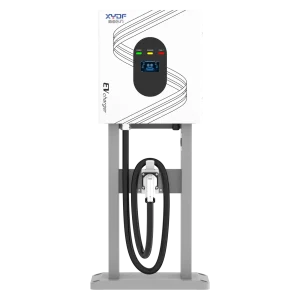

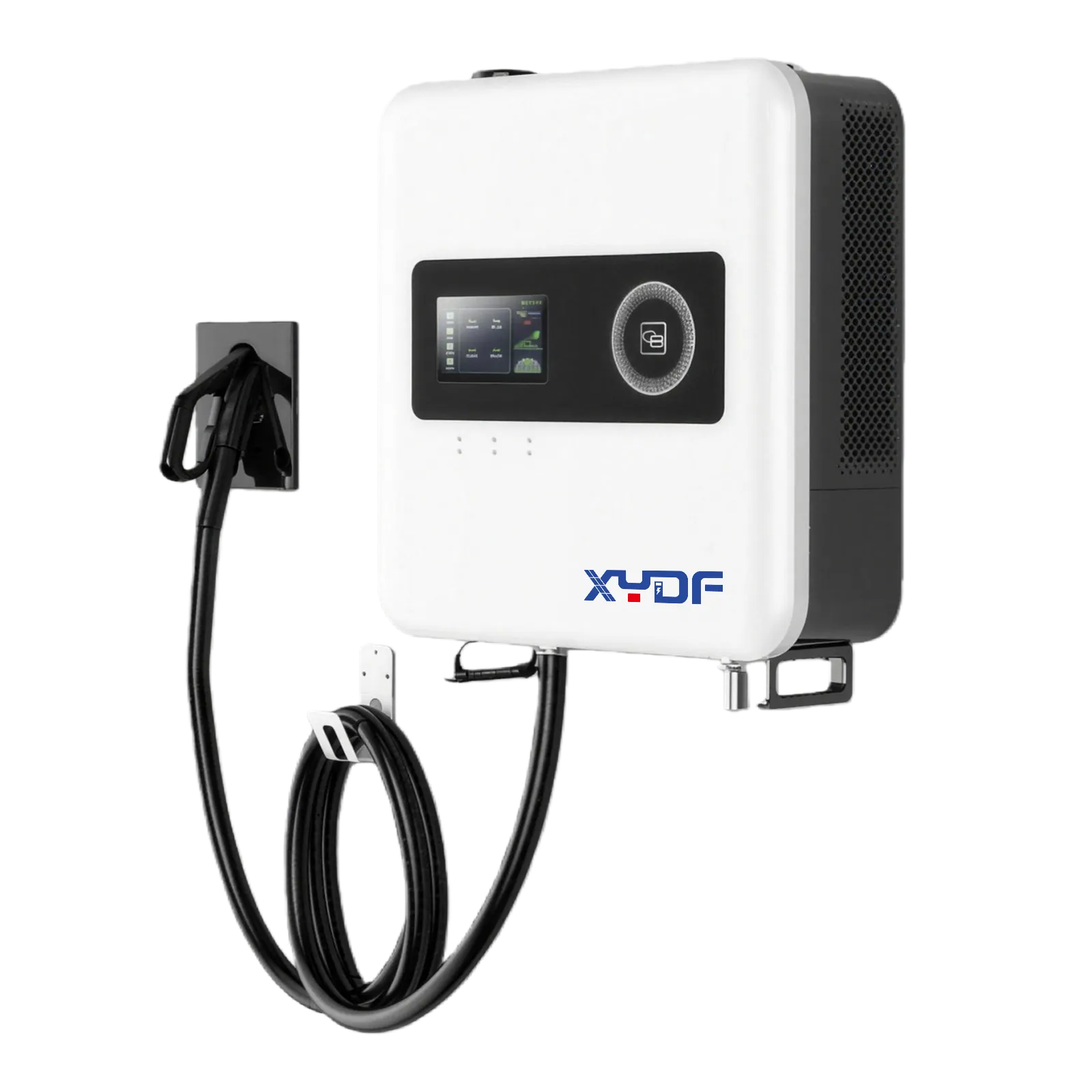
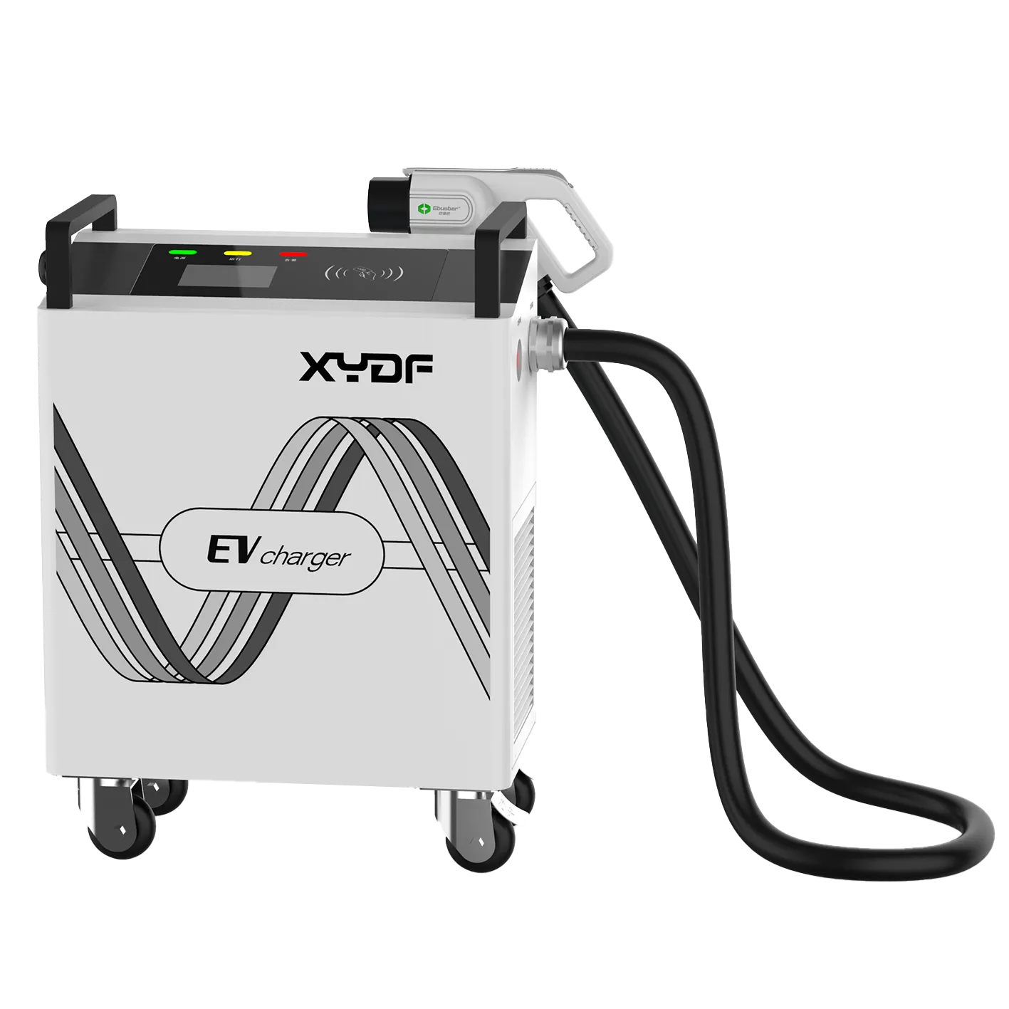
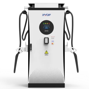
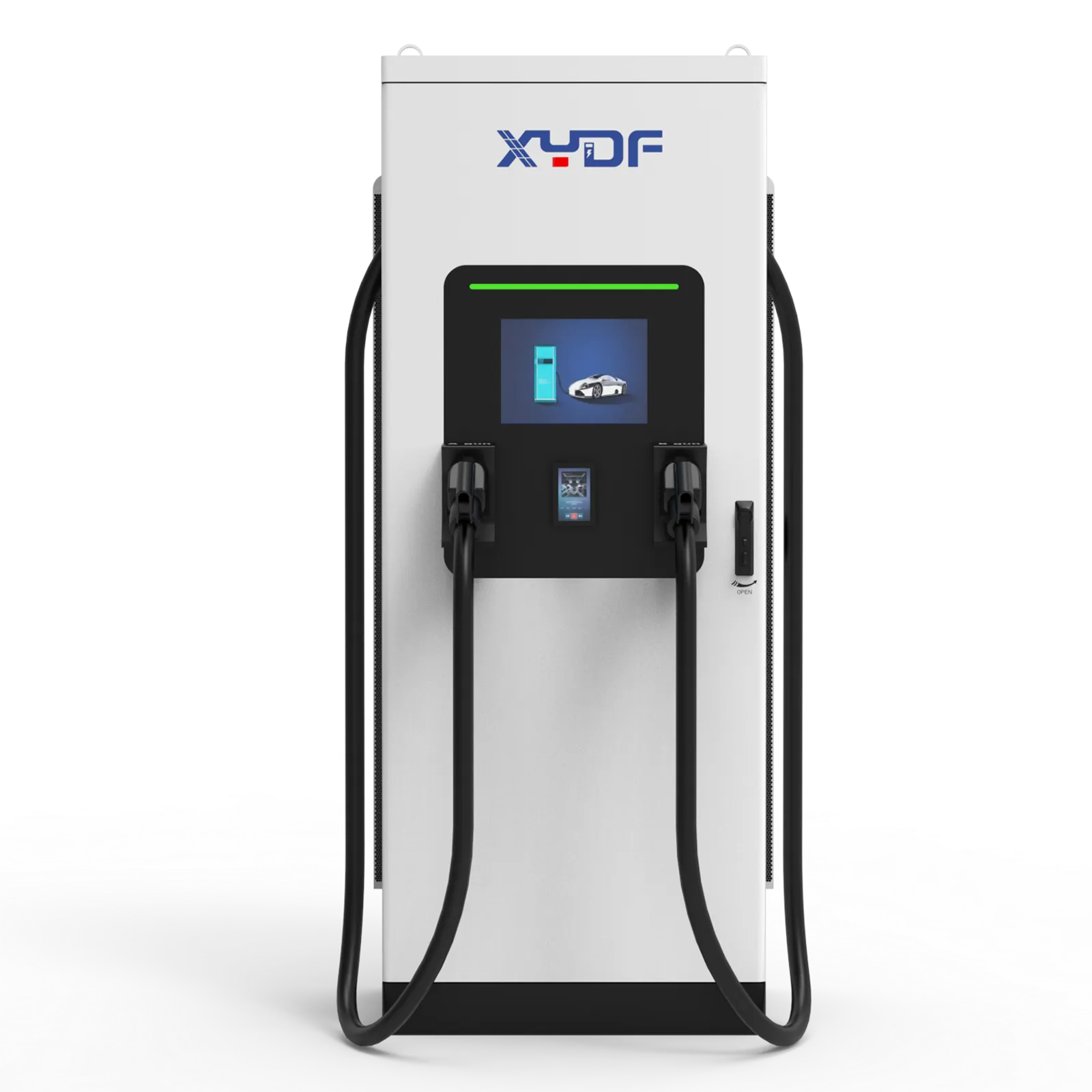
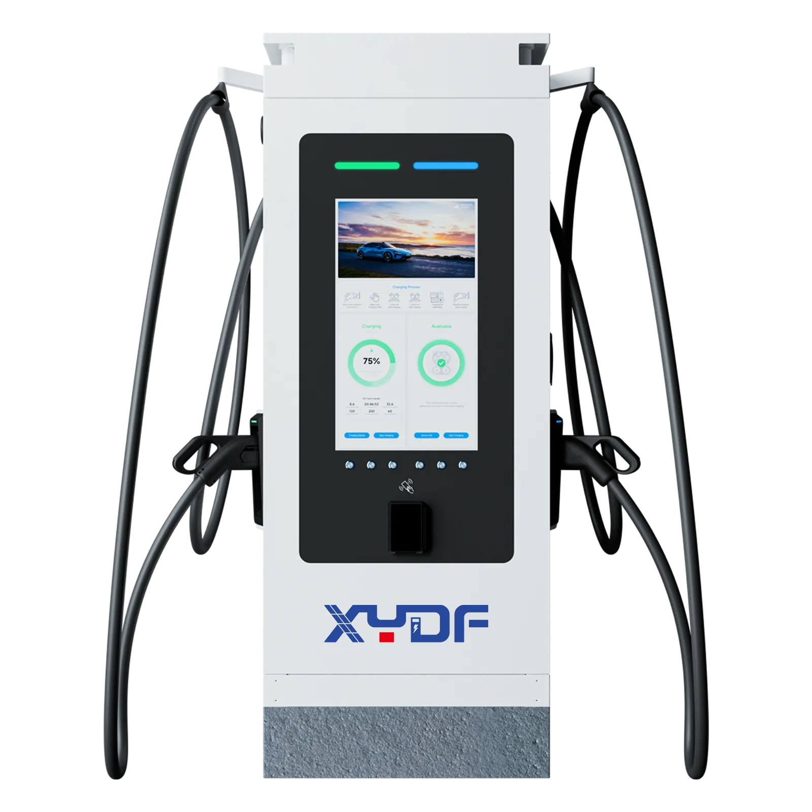
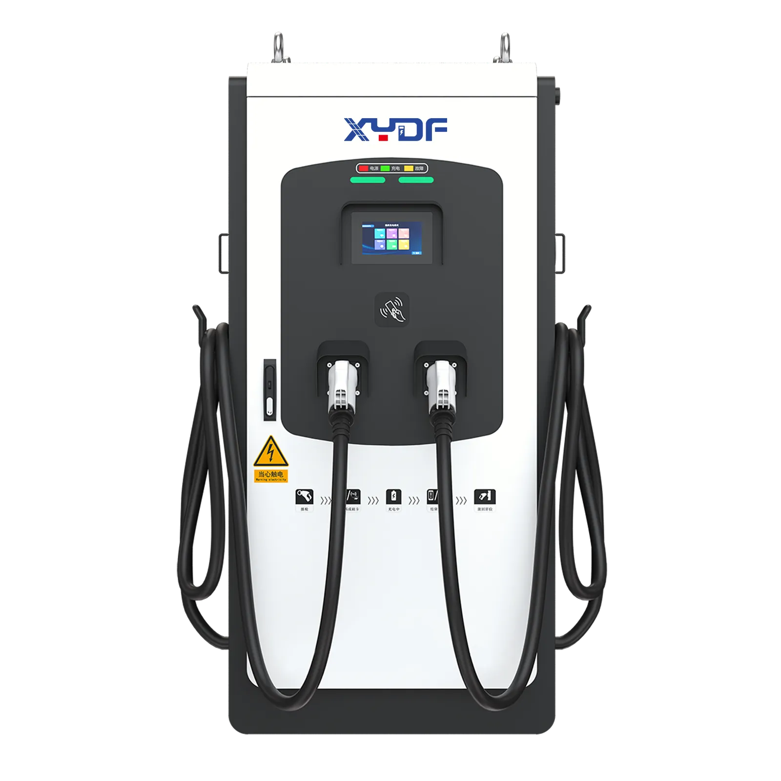
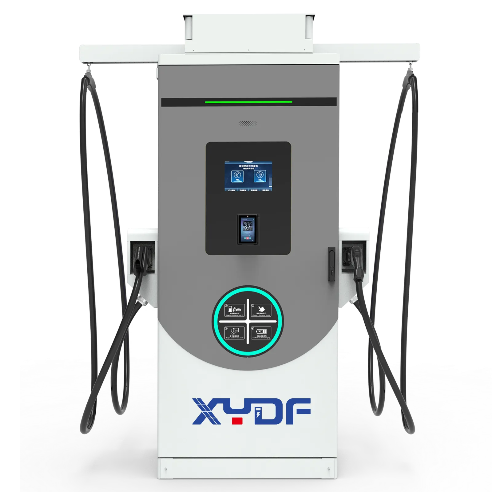
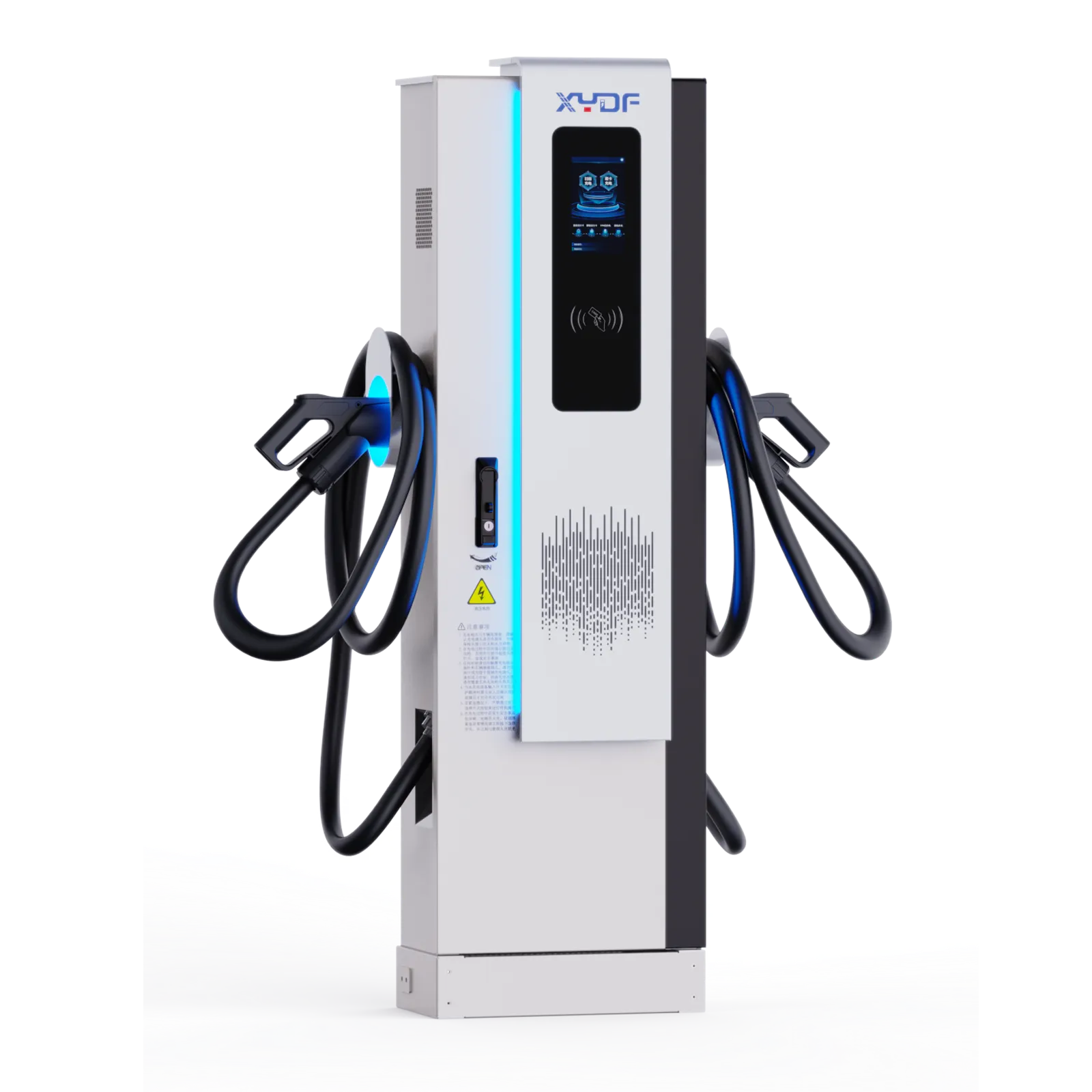
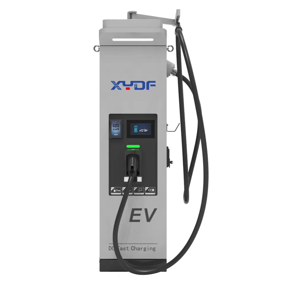
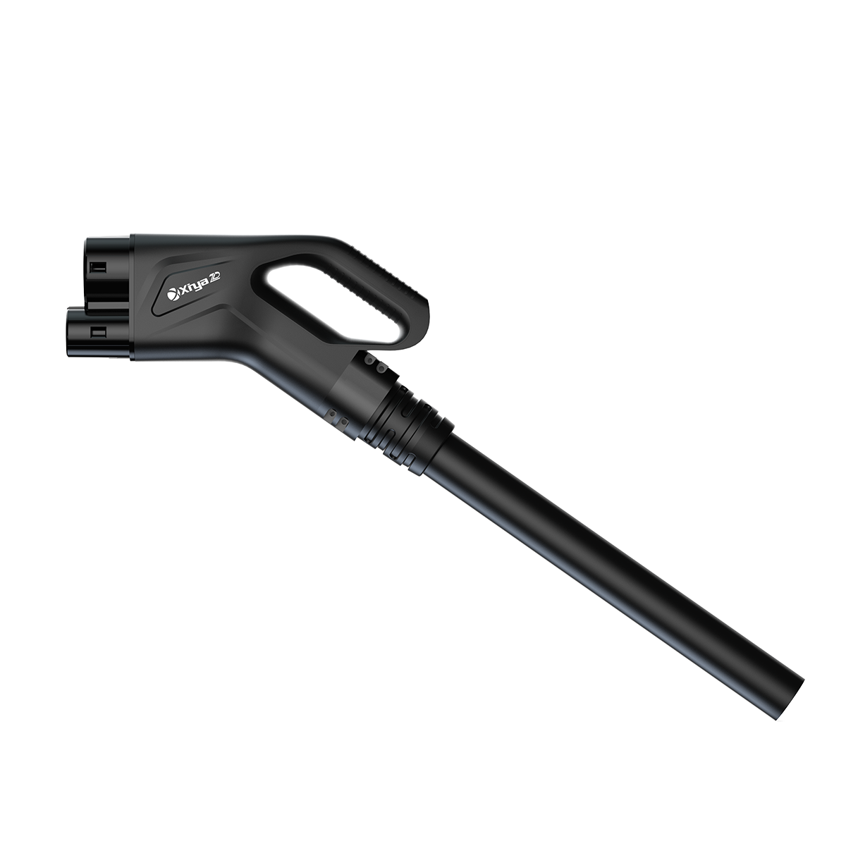
Summary: A 350kW charger rating is the charger’s maximum output capability under suitable conditions; it is not a guaranteed real-time charging speed for every EV. Actual power is normally the lowest active limit in the vehicle, connector, charger, cabinet, and site power chain—so the useful acceptance criterion is vehicle-requested power versus measured charger output, not a nameplate comparison alone. Test at low SOC with a thermally ready, high-power-capable EV or a calibrated EV simulator, one connector active, and backend limits documented. IEC 61851-23:2023 and IEC 61851-24:2023 cover DC EV supply equipment and its control communication; they do not promise that every connected EV will take the charger’s maximum rating.
DC fast charging follows a curve, not a flat line. A charger may advertise 350kW peak capacity, but the vehicle decides how much power it will request at any moment. That request changes as the battery state of charge rises, battery temperature shifts, the power cabinet shares capacity, and the station backend applies load-management rules. The U.S. Department of Energy’s Alternative Fuels Data Center describes the battery-management system as monitoring voltage, current, temperature, and state of charge while charging, which is why those variables belong in any performance diagnosis.
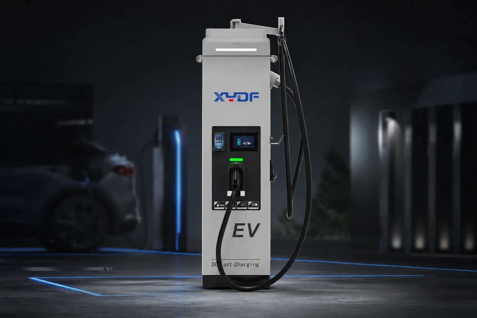
1. A 350kW Nameplate Is Charger Capacity, Not Guaranteed Session Power
A 350kW nameplate means the charger-side DC system can theoretically deliver up to 350kW under defined operating conditions. It does not mean every vehicle connected to the charger will receive 350kW from plug-in to unplug.
In a DC charging session, the charger and vehicle communicate continuously. The vehicle’s battery management system, or BMS, requests the voltage and current it can safely accept. The charger then responds within its own hardware limits, connector limits, thermal limits, and site-level configuration.
For diagnosis, express the ceiling as a limit stack: available power is no greater than the EV’s requested power, the charger’s rated power, charger voltage multiplied by its current ceiling, connector/cable voltage multiplied by its current ceiling, the cabinet allocation, or the site cap. The binding value can change during the same session. This lowest-active-limit rule prevents a buyer from treating one observed kW value as proof of either charger failure or charger compliance.
Relevant standards include:
- IEC 61851-23 — DC EV charging station requirements
- IEC 61851-24 — digital communication between DC charging station and EV
- IEC 62196 — plugs, socket-outlets, vehicle connectors, and inlets
| Vehicle Architecture | الجهد | حالي | Approximate Power |
|---|---|---|---|
| 400V EV | 400V | 212A | 85kW |
| 800V EV | 800V | 437.5A | 350kW |
This explains why a fast charging station for EV deployment may look underpowered during commissioning even when the charger is functioning correctly. If the test vehicle is a 400V EV with a BMS current limit near 200–300A, it may only accept 80–150kW, even on a 350kW charger.
For buyers, the practical lesson is clear: charger power rating, vehicle voltage platform, and BMS request must be evaluated together.
Pack voltage is not a fixed marketing label. The instantaneous voltage shown in the charging log should be multiplied by requested current and compared with measured DC output. At 400V, 212.5A is 85kW; at 800V, the same 212.5A is 170kW. Conversely, 350kW at 800V requires about 437.5A, while 350kW at 400V requires about 875A. These are electrical calculations, not predictions of what a specific vehicle will request.
2. The EV Battery, Not the Charger, Often Controls the Charging Curve
The charging curve is the changing power level during a charging session. In many EVs, power is highest at a low state of charge, then tapers as the battery fills. This tapering protects the battery from overheating, lithium plating, and excessive stress.
A typical high-power window may occur around:
- 10–50% SOC
- 10–60% SOC
- Sometimes up to 70%, depending on vehicle design
After 80% SOC, many EVs reduce charging power significantly. A vehicle that accepts 180kW at 15% SOC may accept only 60–90kW at 75% SOC. That does not mean the electric fast charging station is failing; it usually means the battery is limiting the session.
What the BMS controls
The BMS may adjust charging power based on:
- Battery SOC
- Cell voltage balance
- Pack temperature
- Maximum current acceptance
- Battery chemistry
- Thermal-management capacity
- Manufacturer-defined battery-protection strategy
Battery temperature also matters
Cold or hot batteries can trigger thermal derating. In winter, a cold battery may not accept high power until it is preconditioned. In hot weather, battery or charger thermal protection may reduce current to prevent overheating.
SOC and temperature should therefore be treated as test conditions, not footnotes. Record starting and ending SOC, whether the vehicle preconditioned the pack, ambient temperature, and battery temperature when the vehicle exposes it. If the BMS request is already near 85kW, the charger cannot be judged against 350kW from that session; if the EV requests substantially more than the charger delivers, the investigation moves downstream to the charger, cable, module, cabinet, backend, and grid limits.
ISO 15118 supports vehicle-to-grid communication and Plug & Charge functions, but even with advanced communication, the battery still defines the safe charging request. The charger cannot force the EV to accept 350kW if the vehicle requests only 85kW.
For CPOs operating fast charging stations for electric cars, this means customer education and commissioning records are important. Without explaining the charging curve, users may wrongly assume that a 350kW label means constant 350kW power.
3. Connector, Cable Cooling, and Voltage Platform Create Hard Limits
Hardware creates another set of limits. Even if the charger cabinet supports 350kW and the vehicle can theoretically accept high power, the connector, cable, cooling system, and vehicle inlet must all support the session.
In Europe, high-power DC charging commonly uses CCS2, which is covered under the IEC 62196 connector framework. In global projects, buyers may also encounter:
- CCS1 — common in North America
- CCS2 — common in Europe and many other markets
- GB/T — China market
- CHAdeMO — older Japanese and global legacy deployments
Cable current ratings are critical. Common examples include:
- 200 أمبير
- 300أ
- 500 أمبير
For sustained high-current output, liquid-cooled cables are often required. A non-liquid-cooled cable may not safely carry high current for long periods, especially in hot environments or high-utilization stations.
400V versus 800V platforms
A 350kW charger is most useful when serving vehicles that can take advantage of higher voltage. An 800V EV can reach high power with lower current than a 400V EV at the same power level.
For example:
$$350kW = 800V \times 437.5A$$
For a 400V EV to reach 350kW, the current would need to be extremely high:
$$350kW = 400V \times 875A$$
That current level is beyond many vehicle inlets, cables, and charger configurations. Therefore, a dc fast charger station may be technically rated at 350kW while many real-world 400V vehicles still receive far less.
The honest answer is that 350kW charging is not only about the charger; it is about the whole chain: grid, cabinet, cable, connector, vehicle inlet, BMS, and battery pack.
4. Site-Level Power Sharing Can Turn One 350kW Charger into Multiple 85kW Sessions
Many high-power charging sites use a power cabinet and multiple dispensers. The number shown on the cabinet does not always equal the power available at every connector at the same time.
For example, a 350kW power cabinet serving four charging points may allocate power equally under certain conditions:
$$350kW \div 4 = 87.5kW$$
That looks very close to the 85kW complaint in the Milan commissioning story. If several vehicles are charging at the same time, the system may distribute available power across sessions. Depending on backend settings, the allocation may be equal, priority-based, SOC-based, tariff-based, or fleet-schedule-based.
What CPOs should check
For dc fast charging stations, buyers should distinguish between:
- Cabinet maximum power
- Dispenser maximum power
- Connector maximum power
- Simultaneous output power
- Grid connection capacity
- قدرة المحول
- Backend load-management limits
- Charger module availability
OCPP and backend settings
OCPP 1.6J and OCPP 2.0.1 support remote monitoring, smart charging, load management, transaction control, and charging-profile configuration. If a backend limit is set to reduce peak demand, the charger may intentionally cap output below its nameplate rating.
The Open Charge Alliance’s current protocol page also lists OCPP 2.1, released in 2025, alongside OCPP 1.6 and OCPP 2.0.1. Version selection should follow the charging-management system’s supported feature set and certification requirements; a newer protocol does not by itself raise the charger’s electrical output.
A 350kW charger limited to 85kW by site policy is not underperforming; it is following configuration. That is why commissioning should include backend log review, charger-side measurements, and controlled single-vehicle testing.
Procurement documents should state simultaneous power per active connector for the expected operating modes, not only cabinet peak power. Ask for an allocation matrix covering one, two, and all connectors active, including the minimum module increment, priority rules, recovery after a session ends, and any site or backend cap. OCPP can carry smart-charging profiles and operational data, but the protocol version by itself does not prove a particular power-sharing policy or that a backend has been configured correctly.
5. Hidden Costs and ROI: Why Misreading the Curve Hurts CPO Profitability
For CPOs and EPC contractors, misunderstanding charging curves creates hidden costs. If the site owner expects every session to run at 350kW, normal real-world charging behavior may look like failure. That can lead to unnecessary disputes, warranty claims, and poor customer reviews.
Oversizing cost
Overconfiguring a site can increase:
- Charger CAPEX
- قدرة المحول
- Switchgear cost
- Utility connection cost
- رسوم الطلب
- Liquid-cooling maintenance
- Civil works and cabling cost
Undersizing cost
Underconfiguring a site can create:
- Longer queues
- Lower session throughput
- Negative driver experience
- Missed fleet schedules
- Lower utilization revenue
- Future upgrade costs
ROI depends on delivered energy, not peak kW
Charging-station economics should focus on average delivered kWh per day, not only peak charger rating. A site with excellent utilization at 85–150kW may outperform a poorly located 350kW site with low traffic.
The more useful unit is saleable session energy within the dwell-time window. Session energy is the area under the power-versus-time curve: as an illustrative calculation, an 85kW average sustained for 20 minutes delivers about 28.3kWh before considering metering boundaries and losses. Compare expected kWh per session, sessions per day, utilization, electricity and demand charges, payment/backend fees, maintenance, and financing; do not build the business case by multiplying 350kW by every occupied minute.
For a buyer comparing cabinet sizes, model at least three cases: the vehicle mix accepts less than the charger can offer, the site cap binds during coincident sessions, and the charger can serve a high-voltage vehicle at its contracted envelope. The purchase decision should be based on incremental sellable kWh and avoided queue time versus the incremental grid, equipment, and service cost. This keeps the calculation auditable without inventing energy prices or utilization assumptions.
6. Why a 350kW Charger May Deliver Only 85kW: Buyer Checklist
| Factor | Why a 350kW Charger May Deliver Only 85kW | What Buyers Should Check |
|---|---|---|
| Vehicle voltage platform | 400V EVs may need high current to reach high power | Confirm whether test EV is 400V or 800V |
| BMS current request | Vehicle may request only 200–250A | Review charger logs and BMS request data |
| Battery SOC | High SOC causes power tapering | Test around 10–30% SOC |
| Battery temperature | Cold or hot battery triggers derating | Precondition battery before testing |
| Connector/cable rating | Cable may not support sustained high current | Check 200A, 300A, or 500A cable rating |
| Power sharing | Multiple dispensers may divide cabinet power | Test single-connector and multi-connector modes |
| OCPP/backend limit | Backend may cap output for load management | Review OCPP charging profiles |
| Grid connection capacity | Utility connection may limit station output | Verify transformer and switchgear capacity |
| Charger module availability | Failed or disabled modules reduce output | Check module status and alarms |
| Commissioning test method | Wrong vehicle or high SOC gives misleading results | Use a controlled test protocol |
This table should be part of the commissioning checklist for any high-power EV Fast Charging station. It turns a vague complaint — “the charger is slow” — into measurable engineering questions.
Acceptance evidence that separates EV limits from charger limits
A useful site acceptance record should preserve the timestamped EV request and charger response, measured DC voltage and current, starting and ending SOC, battery and ambient temperature when available, connector and cable used, active sessions, cabinet allocation, module status, backend charging profiles, alarms, and site-meter or power-analyzer readings. Where the contract requires a rated-output demonstration, use a calibrated EV simulator or load bank within its stated voltage/current envelope, then run separate vehicle interoperability sessions; a real EV alone cannot command an arbitrary test point.
The acceptance report should define tolerances, measurement points, instrument identification and calibration status, test duration, pass/fail rules, and the applicable standard or contractual method before testing begins. India’s official AIS-138 Part 2 DC charging-system test document is one public example that calls for periodic measurements of output power and current during tests; it is evidence of a test-method approach, not a universal certification or a substitute for the destination market’s requirements.
7. Application Matrix: Matching Charger Power to Site Type
| Site Type | Typical Charger Power | Best Fit | Technical Note |
|---|---|---|---|
| Retail parking | AC / 22kW / 60kW | Longer dwell-time users | Lower power may be enough if vehicles stay 1–3 hours |
| Highway service area | 180kW / 240kW / 350kW | Short-stop travel charging | 350kW is valuable for 800V vehicles and high traffic |
| مستودع الأسطول | AC / 60kW / 120kW | Overnight or scheduled charging | Load management matters more than peak output |
| Taxi / ride-hailing hub | 120kW / 180kW / 240kW | High turnover urban charging | Dwell time and queue control are critical |
| Urban CPO site | 60kW / 120kW / 180kW | Mixed public charging | Balance grid cost and utilization |
| Logistics yard | 120kW / 240kW / higher planning | Vans and medium-duty fleets | Charging windows may be route-dependent |
| Destination charging | AC / 22kW / 60kW | Hotels, malls, offices | Lower power can match long parking time |
| Heavy-duty or bus depot | 240kW / 350kW / megawatt-level planning | Bus, truck, and high-energy fleets | Requires early utility coordination |
Not every site needs a 350kW charger. For some applications, a smaller fast charging station for EV deployment delivers better ROI because grid cost, dwell time, and utilization align more closely with driver behavior.
8. Standards and Compliance: What Professional Buyers Should Verify
EV charging infrastructure must be designed around electrical safety, connector compatibility, communication protocols, grid requirements, and regional compliance. Standards do not guarantee business success, but they reduce commissioning risk and support professional procurement review.
Key standards and frameworks
| Standard / Framework | Scope | لماذا هذا مهم |
|---|---|---|
| IEC 61851-1 | General conductive EV charging requirements | Defines basic EVSE safety and charging modes |
| IEC 61851-23:2023 | DC charging station requirements | Critical for DC charger design and operation |
| IEC 61851-24:2023 | DC charger-to-EV communication | Supports safe current and voltage negotiation |
| IEC 62196 series, including IEC 62196-3:2026 | Plugs, connectors, inlets; Part 3 covers DC and combined AC/DC vehicle couplers | Relevant for CCS2 and connector compatibility |
| ISO 15118 | EV communication and Plug & Charge | Supports advanced vehicle-grid communication |
| أو سي بي بي 1.6 ج / أو سي بي بي 2.0.1 | Charger-backend communication | Enables monitoring, billing, smart charging |
| EN 61851 / EN 62196 | European adoption of IEC frameworks | Important for EU deployment planning |
| CE marking awareness | EU conformity framework | Required for EU market access planning |
| UL 2202 / UL 2594 | North American charger safety references | Relevant for U.S. and Canada projects |
| SAE J1772 | North American conductive charging interface | Important for Type 1 / CCS1 markets |
| NEC Article 625 | U.S. EV charging installation rules | Relevant to electrical installation compliance |
| GB/T 20234 | China conductive charging connection system | Relevant for China and compatible projects |
| GB/T 27930 | China charger-BMS communication | Important for GB/T DC charging systems |
Commercial risks of poor compliance planning
If standards and documentation are ignored, buyers may face:
- Commissioning failure
- CPO complaints
- Payment and backend mismatch
- Load management failure
- Connector incompatibility
- Overheating or nuisance tripping
- Failed utility approval
- Insurance or inspection risk
- Delayed site opening
- ROI miscalculation
For global buyers, compliance planning should begin before equipment selection, not after site installation.
Edition control matters. As of the 17 September 2026 search cut-off, the IEC catalogue lists IEC 61851-23:2023 for DC EV supply equipment, IEC 61851-24:2023 for digital communication controlling DC charging, and IEC 62196-3:2026 for DC and combined AC/DC vehicle couplers. A purchase specification should name the required edition and destination-market deviations; merely writing “IEC compliant” is too ambiguous for acceptance.
9. Selection Guide: How to Avoid Misreading Fast-Charging Performance
1. Test with the right vehicle and battery condition
A 350kW charger should be tested with an EV capable of high-power charging, ideally an 800V-capable model, low SOC, and preconditioned battery. Testing with a high-SOC 400V vehicle may produce misleading results.
2. Separate charger rating from connector rating
Buyers should confirm cabinet power, dispenser power, connector current, and cable cooling. A charger cabinet may support 350kW, while the cable or connector configuration limits actual output.
3. Design around site power, not only charger power
Grid capacity, transformer rating, switchgear, and utility demand charges often define real operating limits. We recommend calculating simultaneous output scenarios before procurement.
4. Require OCPP and commissioning logs
CPOs should request OCPP compatibility, charging-profile visibility, remote diagnostics, load-management settings, transaction logs, and module-status records. These are essential for diagnosing power disputes.
Before factory or site acceptance, agree the OCPP version and profiles, backend endpoint and security configuration, charging-profile hierarchy, meter-value intervals, and which party will export the evidence. The Open Charge Alliance describes OCPP as the communication protocol between charging stations and management systems; it does not replace IEC electrical-safety testing or prove vehicle-side acceptance power.
5. Use average delivered kWh per day as the ROI metric
Peak kW is useful for marketing and high-end vehicles; average delivered energy is what drives station revenue. A balanced site may generate stronger returns than an oversized site with low utilization.
أسئلة متكررة
What is the cost of EV fast charging?
The cost of EV fast charging depends on electricity price, charging network tariff, demand charges, parking fees, and operator pricing strategy. For CPOs, the cost also includes charger CAPEX, grid connection, transformer capacity, maintenance, backend software, and payment processing. A public electric fast charging station may charge by kWh, by minute, by session, or through a membership model, depending on local regulations.
ما هي أسرع محطة شحن للسيارات الكهربائية؟
The fastest EV charging station is typically a high-power DC charger rated around 350kW or higher, but real speed depends on the vehicle. A 350kW charger can only deliver near-peak output when the EV supports the voltage, current, SOC window, and thermal conditions required. In practice, the fastest station is the one that matches high-power vehicles, strong grid capacity, and correct load-management settings.
Is fast charging good for EV?
Fast charging is safe when the vehicle and charger communicate correctly, but frequent high-power charging can increase battery thermal stress over time compared with slower AC charging. Modern EVs use BMS controls to limit current, manage temperature, and taper power. For normal drivers, occasional DC fast charging is useful; for fleets, charging strategy should balance uptime, battery health, and operating cost.
Can any EV charge at 350kW?
No. Most EVs cannot charge at 350kW. The vehicle must support high voltage, high current, suitable battery chemistry, thermal management, and compatible connectors. Many 400V EVs may accept only 80–150kW even when connected to a 350kW dc fast charger station. Some 800V EVs can approach very high charging rates, but usually only in a specific low-SOC window.
What is the fastest charging speed for an electric car?
The fastest charging speed for an electric car depends on both charger rating and vehicle capability. Some high-performance EVs can exceed 250kW, and selected 800V models may approach 300–350kW under ideal conditions. However, that peak usually lasts only part of the charging curve. Average session power is often lower than the maximum number shown on the charger.
What is considered a fast charger for an EV?
In many markets, AC charging around 7–22kW is considered normal or destination charging, while DC charging from about 50kW upward is commonly considered fast charging. High-power DC charging may range from 120kW to 350kW. For commercial planning, a fast charger is not defined only by power; it also depends on connector type, communication standard, payment system, and grid capacity.
How to use EV fast charging station?
To use an EV fast charge station, the driver usually parks, connects the correct DC connector, starts the session through an app, RFID card, payment terminal, or Plug & Charge function, and waits while the vehicle manages the charging curve. For best speed, the EV should arrive with low to moderate SOC, ideally with the battery preconditioned if the vehicle supports it.
Which EV supports DC fast charging?
Most modern battery electric vehicles support DC fast charging, but maximum power varies widely. Some compact EVs may accept 50–100kW, mainstream models may accept 120–200kW, and high-voltage premium models may accept 250kW or more. Buyers planning fast charging stations for electric cars should test multiple vehicle models instead of assuming one charger rating fits all vehicles equally.
How do DC fast chargers work?
DC fast chargers convert grid AC power into DC power outside the vehicle and deliver it directly to the EV battery through a controlled communication process. The EV and charger negotiate voltage and current using standards such as IEC 61851-24, ISO 15118, or regional protocols. The vehicle BMS then adjusts the request throughout the charging curve to protect the battery.
المراجع
- IEC — International Electrotechnical Commission
- IEC 61851-23:2023 — DC electric vehicle supply equipment
- IEC 61851-24:2023 — Digital communication between a DC EV charging station and an EV
- IEC 62196-3:2026 — DC and combined AC/DC vehicle couplers
- ISO 15118 — Vehicle-to-grid communication interface
- CharIN — Charging Interface Initiative
- BloombergNEF — Electric Vehicle Outlook
- U.S. Department of Energy AFDC — How all-electric cars work
- Open Charge Alliance — Open Charge Point Protocol
- ARAI and CEA — AIS-138 Part 2, Electric Vehicle Conductive DC Charging System
A 350kW charger is not a promise that every vehicle will charge at 350kW. It is the ceiling of the charging system under suitable conditions. The real business outcome depends on the charging curve, vehicle voltage platform, BMS current request, SOC, battery temperature, connector rating, site power allocation, and backend configuration.
XYDF manufactures AC and DC EV charging equipment with project documentation support for IEC-based deployment, OCPP integration, connector configuration, power-module planning, and buyer-defined compliance requirements. For broader planning, compare DC fast charger solutions with commercial AC EV charger options, then contact XYDF with the vehicle mix, dwell time, simultaneous-power target, grid limit, and required acceptance evidence.