 Синьцзя Дунфан Электрик Технолоджи Ко., Лтд.


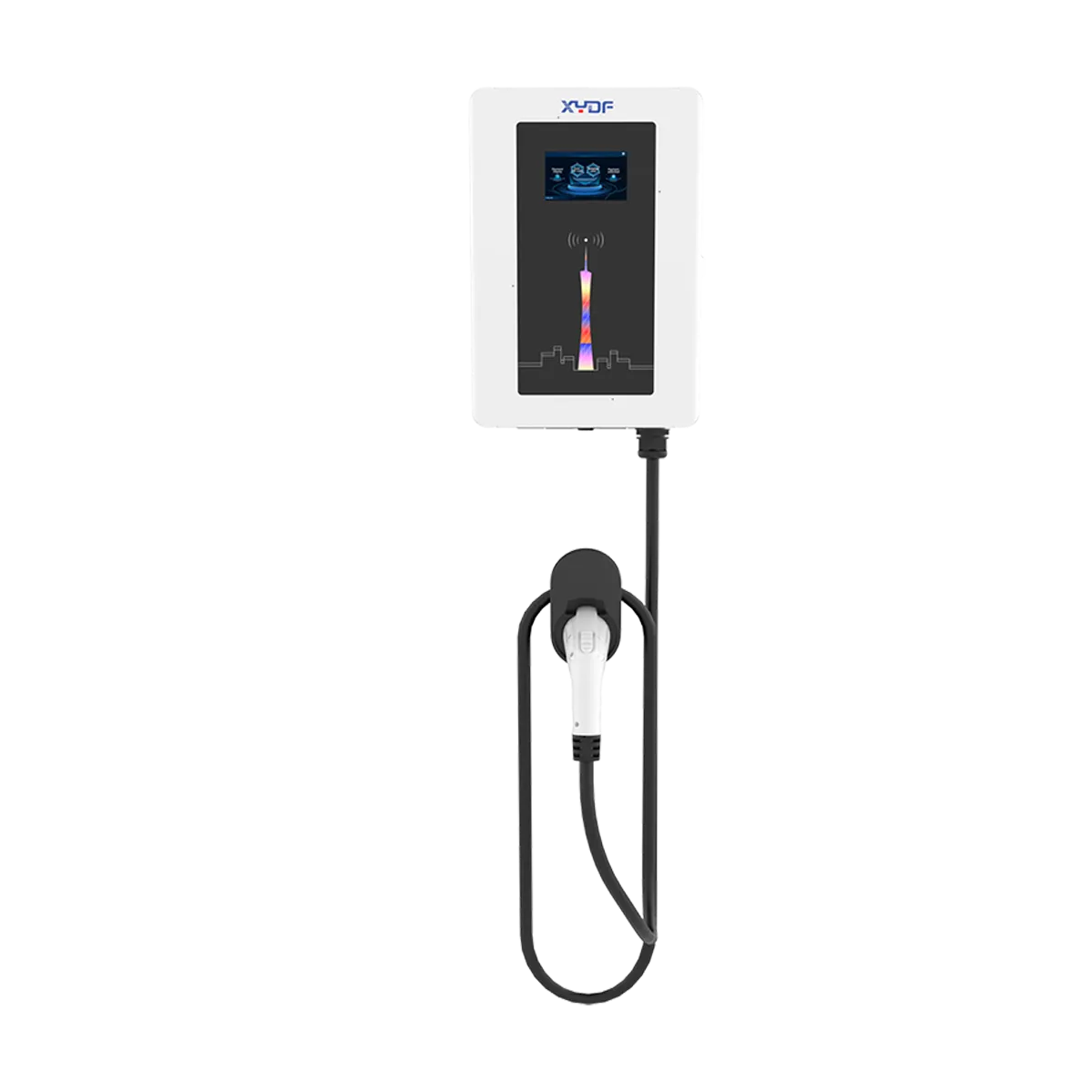
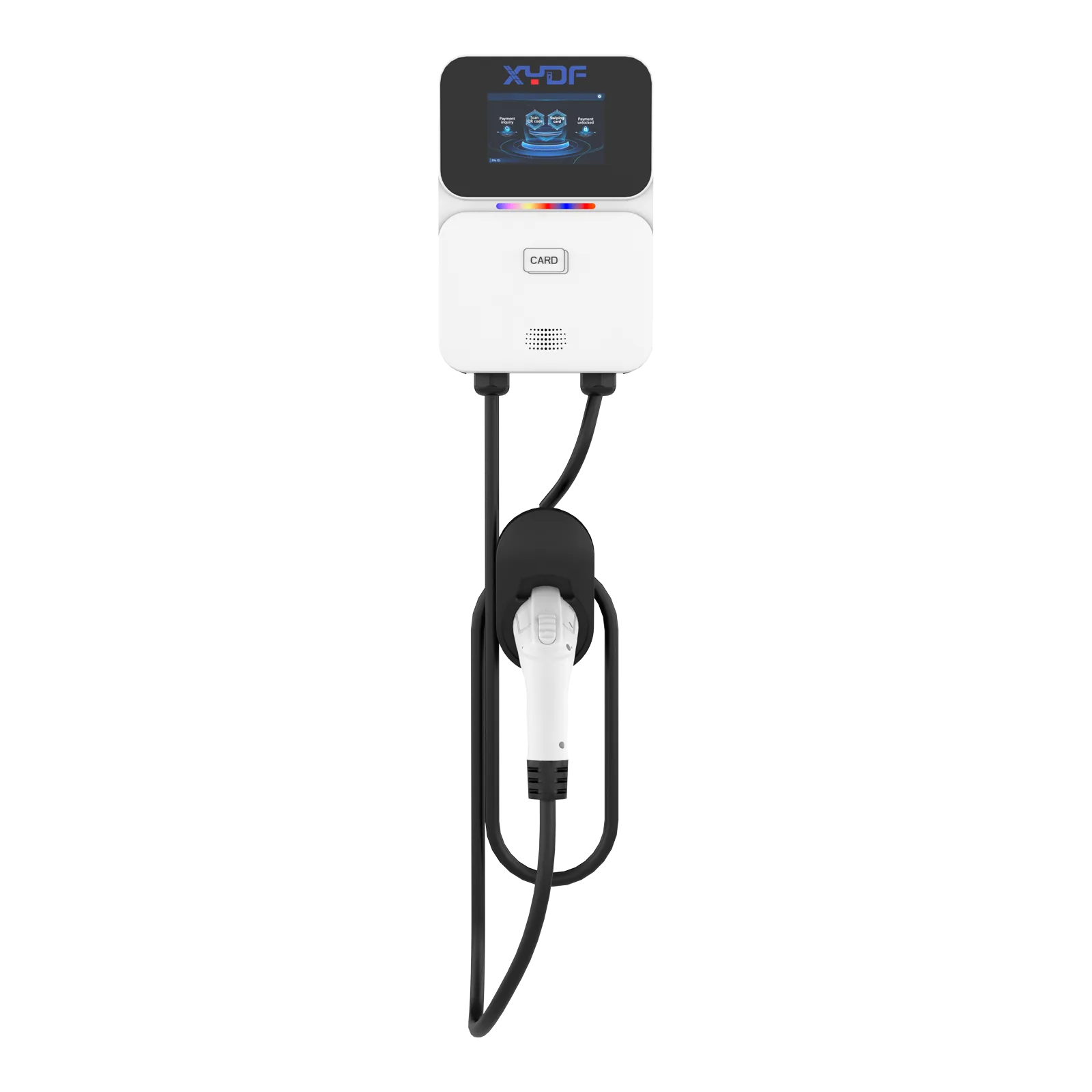
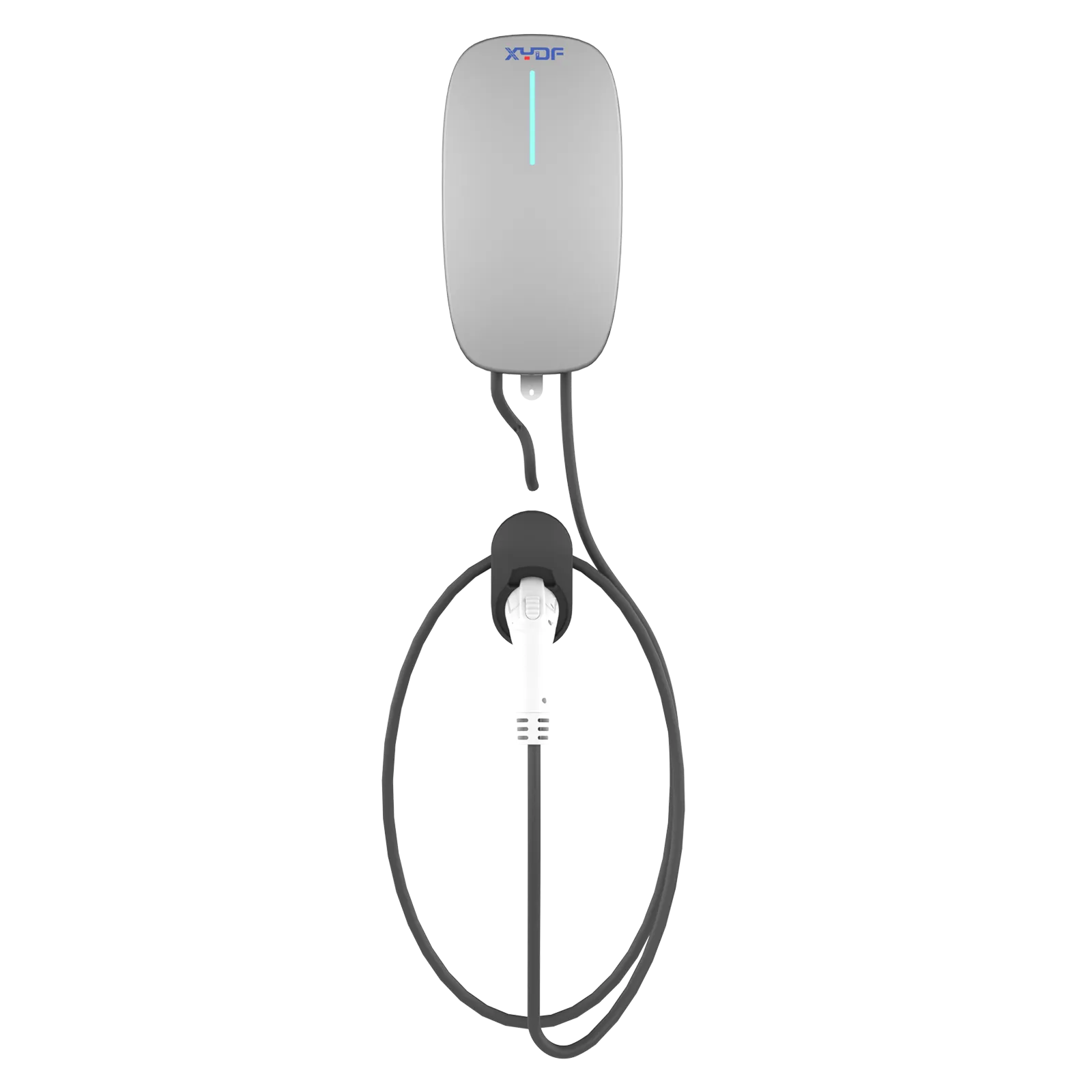
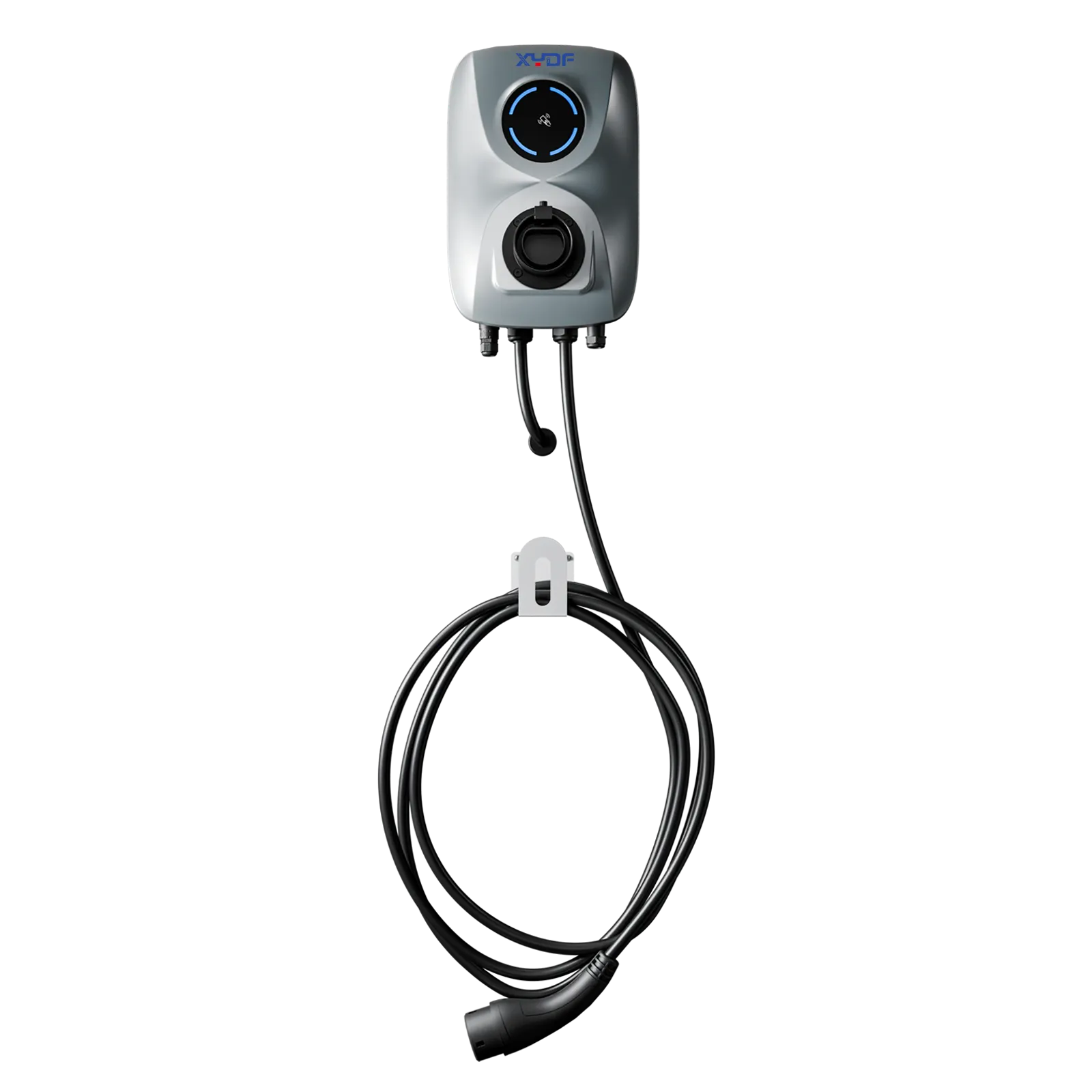
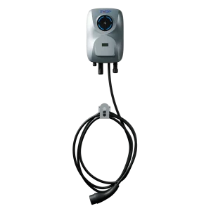
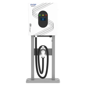

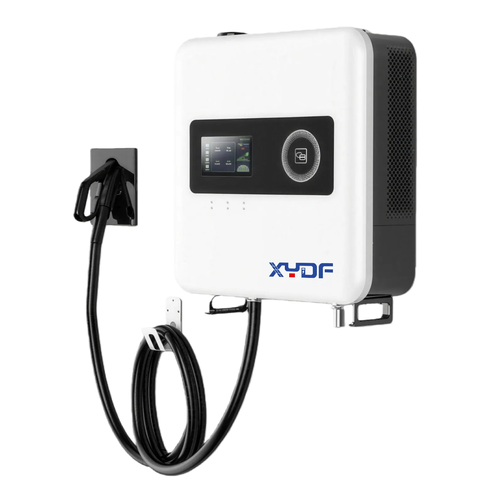
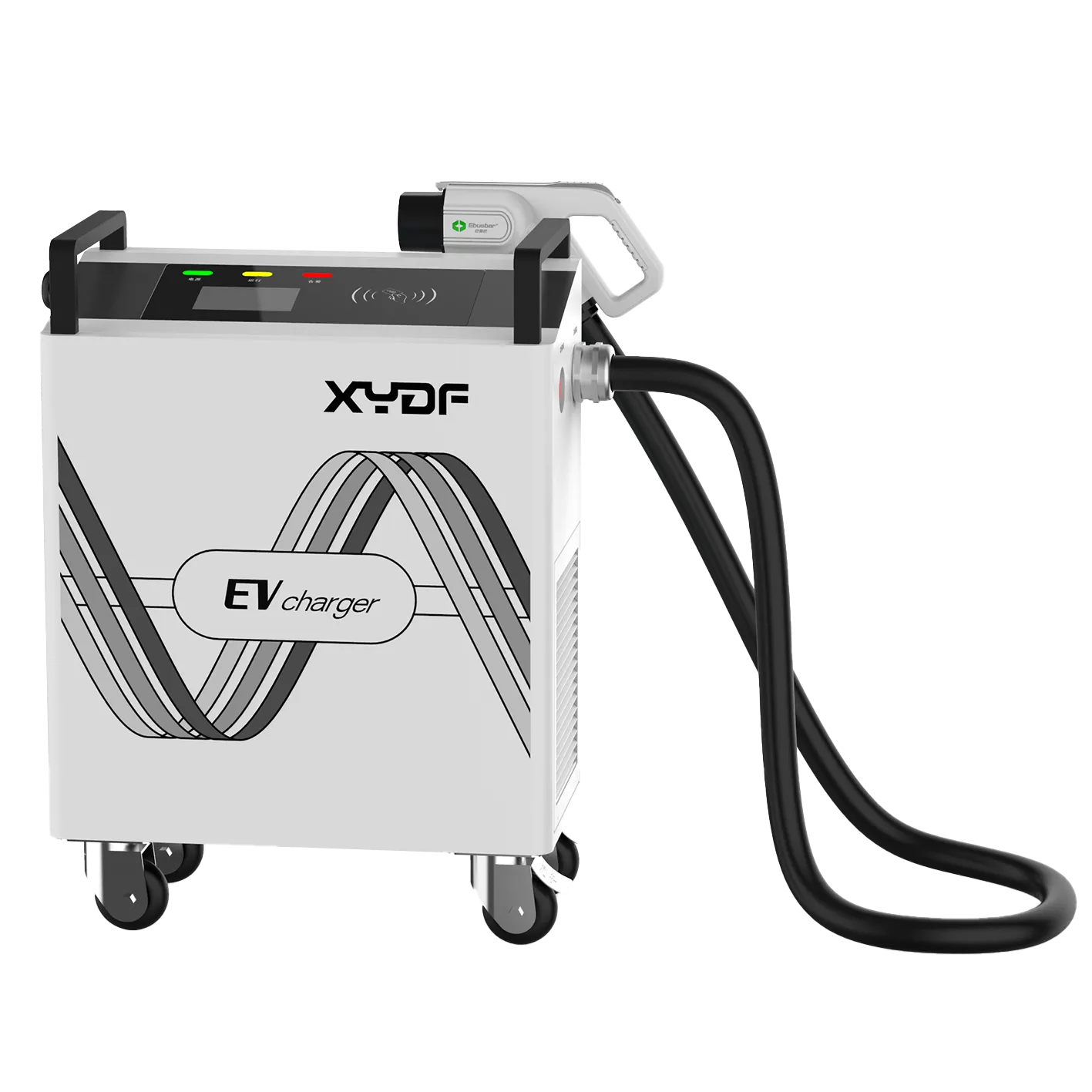
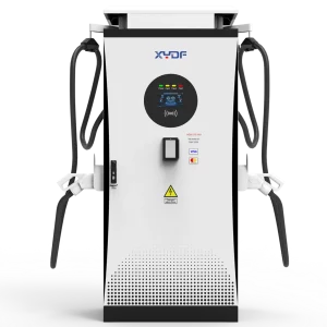
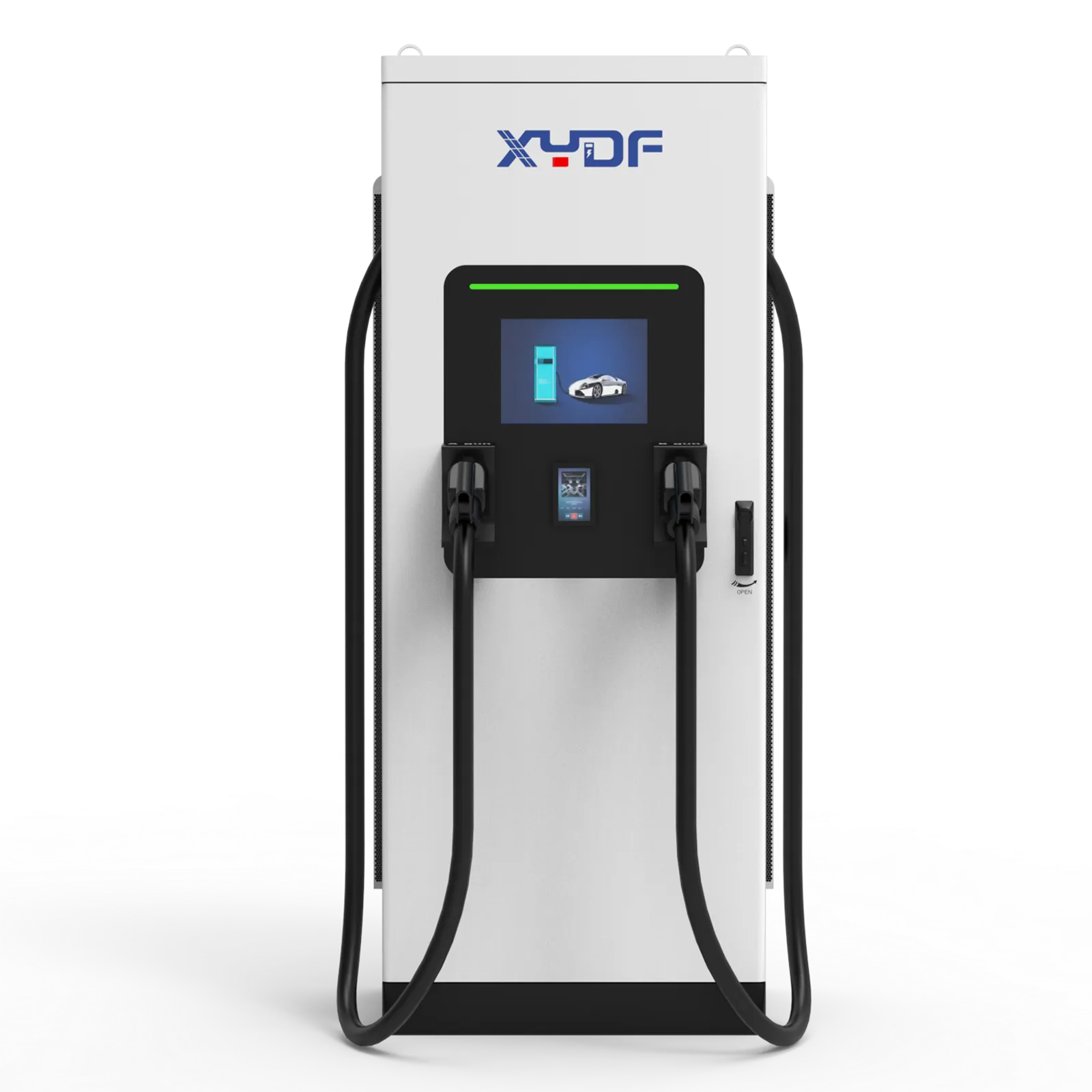
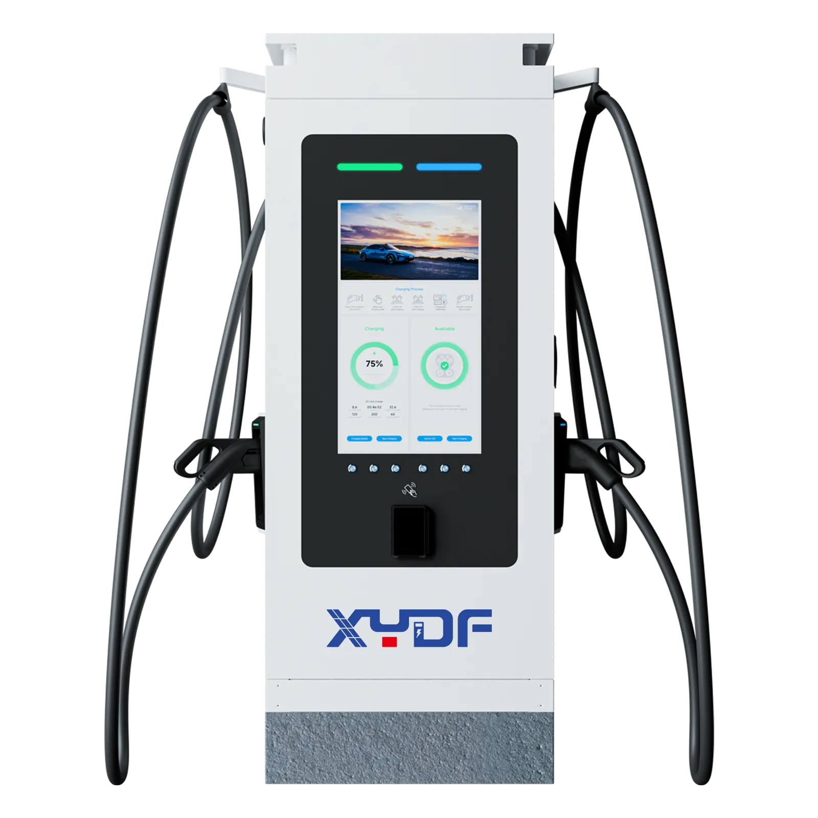
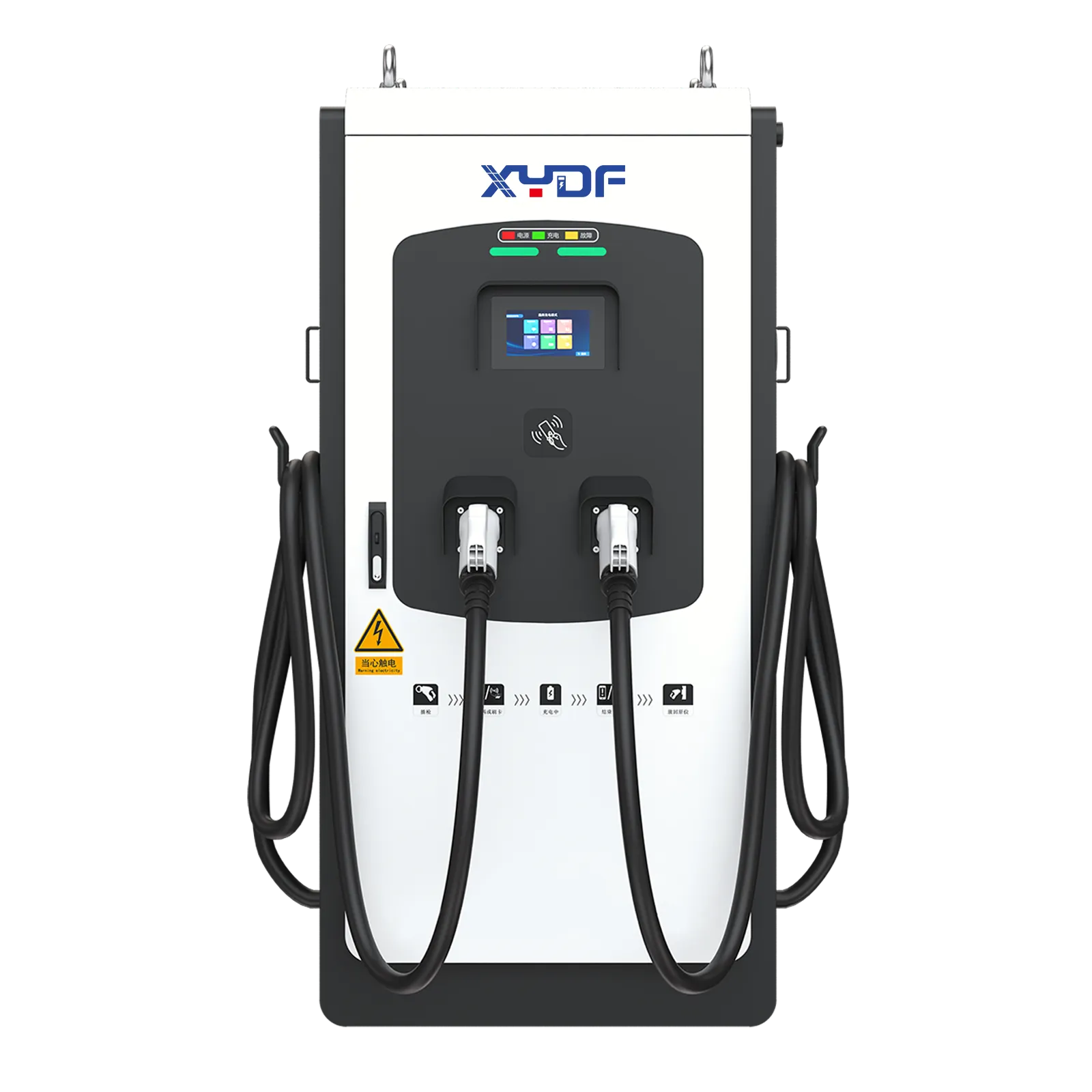
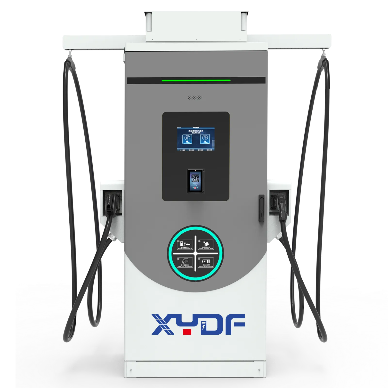
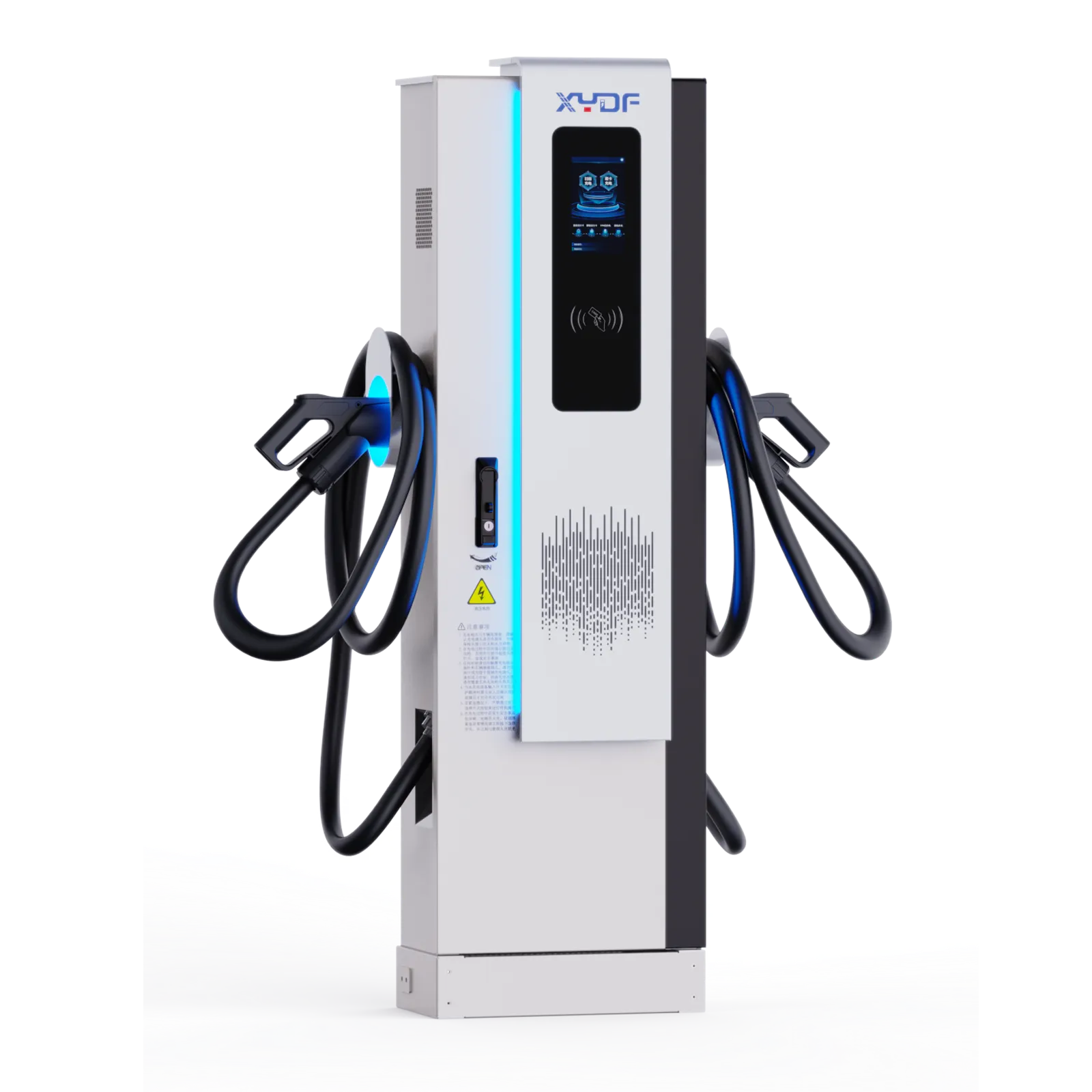
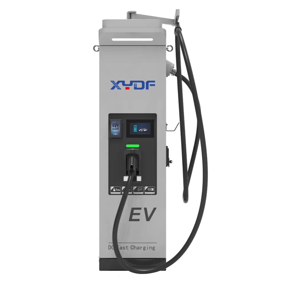
A коммерческая зарядная станция для электромобилей can pass a factory functional test and still be exposed to a site-level transient. A nearby lightning strike, a utility switching event, or a poorly bonded distribution board can put a short-duration overvoltage on the feeder that supplies an EV charging station. The visible result may be a tripped protective device, a failed power module, a damaged communications port, or a station that is unavailable until a board is replaced. The underlying issue is often coordination between the service entrance, grounding and bonding, surge protective devices (SPDs), and the charger’s own design—not simply a “bad charger.” This guide gives commercial operators, site owners, contractors, EPC teams and procurement staff a practical path to decide what protection is required and how to check it.
Short answer: Commercial EV charging stations normally require a documented surge-protection and grounding design, but the exact device class, location and lightning-protection measures depend on the electrical system, exposure, local code and the charger’s installation instructions. IEC 62305 addresses lightning-protection risk management and protection measures, while IEC 61851-1 addresses conductive EV charging equipment; neither standard removes the need to coordinate the complete installation. Verify the utility service entrance, earthing electrode system, bonding paths, SPD ratings and separation distances before energization, then repeat visual and functional checks after a significant storm.
Why can a commercial EV charging station be damaged even without a direct strike?
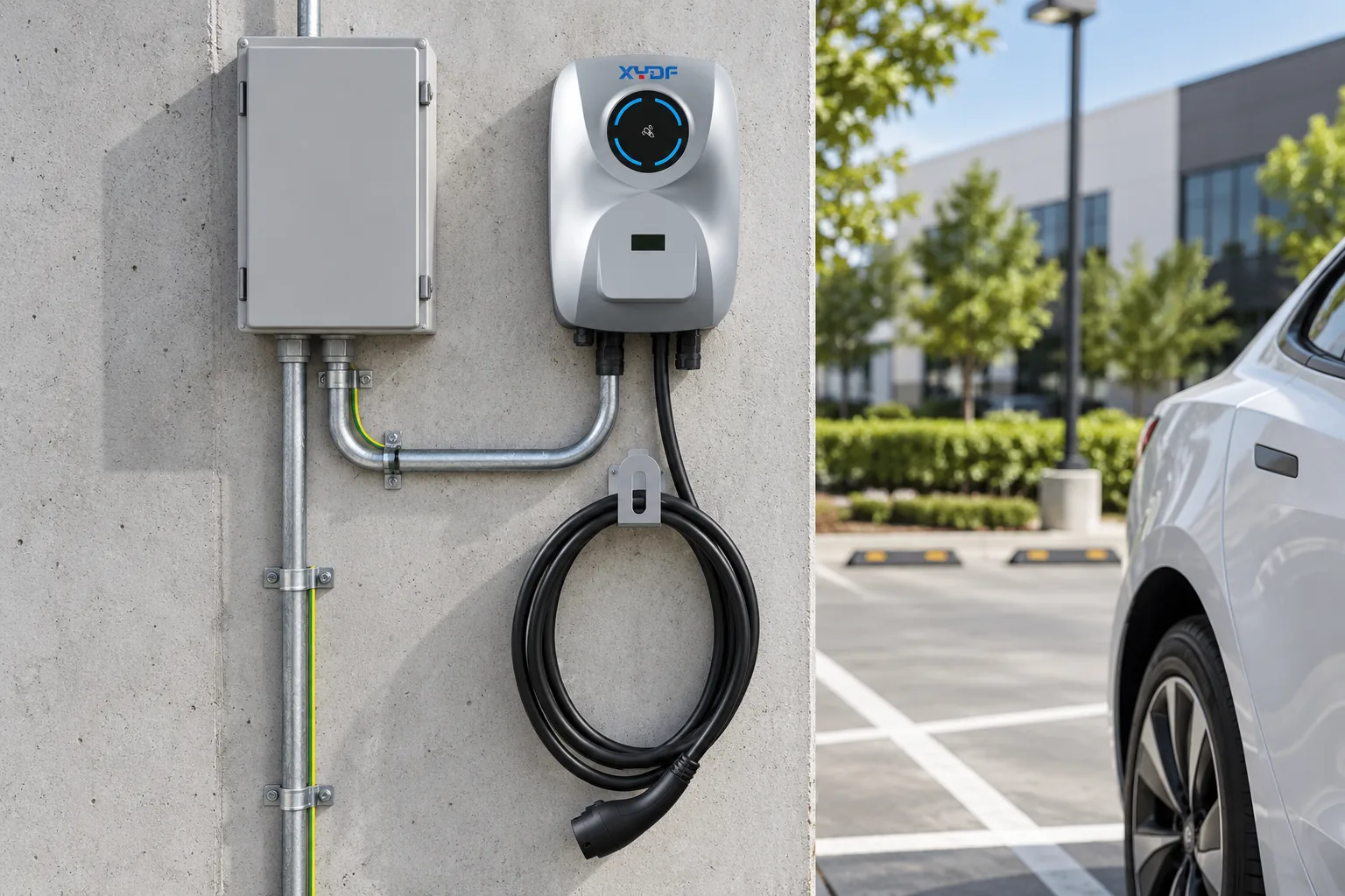
Lightning protection has two different problems to control. A direct strike to a building, pole or nearby conductor can inject substantial current into the site lightning-protection and earthing network. An indirect strike can create an electromagnetic transient in a loop of cable or in an overhead utility circuit. Utility faults and switching operations can also produce transient overvoltages. The charger may never be touched by lightning, yet its AC input, control electronics, Ethernet interface or meter can see a voltage outside its design envelope.
Protection is therefore a system task. The service entrance, sub-distribution board, EV charger feeder, data circuits and exposed metalwork need a deliberate path for transient energy and a common reference potential. A short connection to a suitable bonding point generally performs better than a long, inductive conductor; the final arrangement must follow the applicable code and the SPD manufacturer’s installation instructions.
What is the difference between surge protection and lightning protection?
Surge protection limits transient voltage and diverts surge current through an SPD. Lightning protection is the broader set of measures used to intercept, conduct and disperse lightning current, while reducing dangerous potential differences within a structure. An EV charger lightning protection plan therefore treats the SPD as one component of a wider system; it is not a substitute for air terminals, down conductors, a grounding electrode system, bonding or the separation distances required by a lightning-protection design.
| Exposure or design question | What the protection addresses | What the project team should verify |
|---|---|---|
| Service entrance or main distribution | Limits transient energy entering the site’s distribution system | Service-entrance SPD, upstream fault protection, bonding point and coordination with downstream SPDs |
| Feeder or EV sub-board | Reduces residual voltage on the circuit feeding the charger | Feeder length, cable arrangement, local SPD, backup protection and coordination with the service device |
| Charger-side terminals or internal protection | Limits the voltage that reaches the charger’s power and control electronics | Equipment SPD data, lead routing, accessible status indication and the manufacturer’s wiring diagram |
| Ethernet, RS-485 or other external communications | Protects low-voltage interfaces that can conduct a transient into controls | Shielding/bonding approach, interface SPD where specified, and routing away from lightning-current conductors |
These boundaries are coordinated layers, not interchangeable labels. A service device does not automatically protect a long outdoor feeder or an external data cable, and a charger-side device cannot correct a missing bonding path upstream. The approved single-line diagram should show the path from the service entrance through the feeder and charger terminals, with communications circuits reviewed separately.
How should SPD selection be coordinated for AC and DC fast chargers?
Which SPD parameters matter?
Ан EV charger surge protection specification should identify the system voltage and earthing arrangement, the SPD’s maximum continuous operating voltage, discharge-current capability, voltage-protection level, short-circuit withstand or associated backup device, status indication and replacement method. The project engineer should also confirm whether the EV charging station SPD is intended for the service entrance, a distribution board or equipment-level protection. “Type 1,” “Type 2” and “Type 3” terminology is used differently across regional frameworks, so the tender should name the governing standard and the test classification rather than relying on a label alone.
Where does protection go in an AC charging circuit?
Many sites use a layered arrangement: protection at the utility service or main distribution board, additional protection at an EV sub-board when the feeder and exposure justify it, and equipment-level protection when the charger design calls for it. The layers must be coordinated so that an upstream device does not unnecessarily disconnect before the downstream device can handle the event. Keep the connection between the SPD and the phase, neutral and protective-earth terminals short and direct, and provide the specified overcurrent disconnect and accessible status indicator.
Does a DC fast charger need a different approach?
A DC fast charger still receives AC at its input, so the AC supply and upstream distribution require the same site-level assessment. The charger may also contain isolated power-conversion stages and DC output conductors; any internal or external DC-side SPD must be selected for the voltage and fault conditions stated by the manufacturer. Do not add a generic DC SPD to a high-power cabinet without confirming its maximum continuous voltage, polarity, interrupting capability, creepage/clearance and coordination with the charger’s insulation-monitoring and protection functions.
| Charger type | Primary protection boundary | Additional review |
|---|---|---|
| Зарядное устройство переменного тока | Service entrance, EV feeder and charger AC terminals | Protective-earth continuity, local SPD arrangement and any external communications cable |
| Быстрая зарядка постоянным током | Service entrance, feeder and AC input to the power-conversion cabinet | Manufacturer-defined DC output or internal protection, insulation-monitoring coordination and cabinet bonding |
What makes EV charging station grounding reliable?
EV charging station grounding is more than driving a rod beside the cabinet. The design normally combines a grounding electrode system, a protective-earth conductor sized and routed according to the governing code, and equipotential bonding for the charger enclosure, distribution equipment, cable-management metalwork and any lightning-protection system. The goal is a low-impedance path for fault current and a controlled reference during a transient. A single resistance reading cannot by itself prove that bonding, conductor routing or touch-voltage control is adequate.
How do the grounding electrode, protective earth and bonding differ?
The grounding electrode system connects the installation to earth through the electrodes permitted by the local rules. The protective-earth conductor connects exposed conductive parts to the fault-clearing system. Equipotential bonding connects relevant metalwork and other conductive paths so a transient or fault does not create an avoidable potential difference between them. These roles can be interconnected, but they are not interchangeable terms and should be shown separately on the design documents.
Confirm the site’s earthing arrangement (for example, the local equivalent of TN, TT or IT), the neutral-to-earth treatment, and the disconnection method for an earth fault. Record continuity and bonding tests using the method required by the local code or commissioning specification. Where electrodes, structural steel, utility bonding or lightning conductors are interconnected, the responsible electrical engineer should document the connections and any required separation distance before installation is closed up. A satisfactory electrode resistance result alone does not prove protective-earth continuity, bonding integrity or correct SPD lead routing.
Where should surge protection be installed in an EV charging system?
Location follows the transient path and the coordination study. A service-entrance SPD protects the site’s incoming supply; a downstream device can reduce the residual voltage on a long feeder; and a charger-integrated or adjacent SPD can protect the equipment terminals. If a communications cable leaves the protected zone, it can require a coordinated signal-line protector or a change in routing. The installation drawing should show each device, its bonding point, backup protection, conductor length and status indication.
Place the charger feeder and communications cables so they do not run in parallel with lightning down conductors or other high-current paths unless the design explicitly manages the coupling. Cable shields and metallic glands should be bonded as specified; an improvised shield connection can create a new loop. The final arrangement must be checked against the selected SPD’s installation instructions and the regional electrical rules.
What should a contractor check before commissioning?
The following checklist is suitable for an inspection record. It is a prompt for the responsible licensed electrician or engineer, not a replacement for local code or the equipment manual.
| Check | Evidence to record | Action if incomplete |
|---|---|---|
| Site risk and exposure review | Lightning-risk method, overhead/underground supply notes, site layout and code basis | Have the designer resolve exposure and separation assumptions before energization |
| Service and feeder SPDs | Manufacturer, standard/test classification, ratings, backup device and installation location | Correct the specification or wiring; do not substitute by appearance |
| Grounding and bonding | Continuity results, electrode/bonding diagram, conductor identification and torque records where required | Repair open or high-impedance connections and repeat the prescribed tests |
| Physical routing | Photos or as-built drawing showing SPD lead length, cable separation and enclosure entries | Reroute or reterminate conductors to match the design |
| Charger documentation | Installation manual, wiring diagram, firmware/configuration record and protective-device settings | Obtain the correct revision from the equipment supplier before handover |
| Post-storm readiness | Inspection interval, SPD status indicator check, alarm review and spare/replacement process | Isolate affected equipment safely and investigate before returning it to service |
What is the decision sequence before energization or after a storm?
- Before energization, freeze the approved risk assessment, single-line diagram and charger installation revision.
- Verify each service, feeder, charger-side and communications protection boundary against the specified device data, backup protection and lead routing.
- Complete the prescribed protective-earth, bonding and functional checks, then retain the results with the as-built drawing.
- After a significant storm, place the affected equipment in a safe state and inspect SPD indicators, alarms, protective-device status, enclosures and communications.
- If a status change, trip, physical defect or unexplained fault is found, isolate and investigate with the responsible qualified person; do not repeatedly reset the charger.
- Return the station to service only after the cause, replacement parts and retesting requirements are documented.
Which standards and compliance documents should be in the project file?
Use the standards that apply to the destination market and the installation type. IEC 62305 provides the framework for lightning protection; IEC 61851-1 covers general requirements for conductive EV supply equipment; and NFPA 780 is a US lightning-protection installation standard. National wiring rules, utility requirements, building regulations and fire-safety provisions can add requirements. A standard may describe a test method or design process, and it should not be presented as a blanket product certification.
For procurement, request the exact product data sheet, installation manual, declaration or test report that corresponds to the proposed model and market. Check the voltage system, earthing arrangement, environmental conditions, enclosure requirements and replacement procedure. Unsupported claims about “lightning-proof” operation can create commissioning disputes and warranty ambiguity; the contract should define who owns the site design, installation tests and post-storm decision.
How should a buyer specify protection in an RFQ?
The RFQ should ask for the governing regional equivalents where a project does not use IEC terminology. At minimum, require the system voltage and earthing arrangement, the SPD’s maximum continuous operating voltage (often shown as Uc), voltage-protection level (often shown as Up), the applicable discharge- or current-class designation, backup protection, lead-routing limits, status indication and the replaceability method. These are selection fields, not assumed ratings; the bidder must complete them from the proposed model and site design.
- Describe the supply: nominal voltage, phases, frequency, earthing arrangement, prospective fault current and service-entrance protection.
- Map the site: feeder lengths, outdoor exposure, overhead services, nearby structures, communications routes and any lightning-protection system.
- State the governing standards and require an SPD coordination drawing with Uc/Up or regional equivalents, current class, backup protection and lead-length limits.
- Ask for status indication, replacement access, grounding/bonding test records, charger installation instructions and a clear post-storm inspection process.
- Separate product evidence from site responsibility: the charger supplier can provide equipment data, while the licensed designer confirms the complete installation.
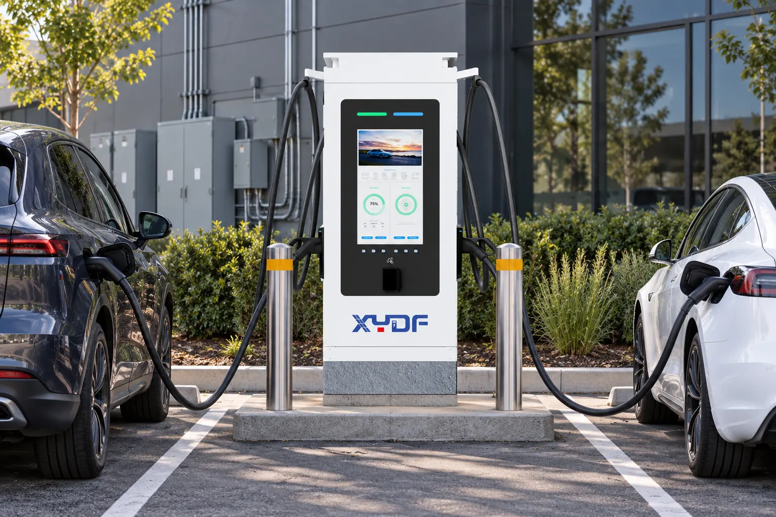
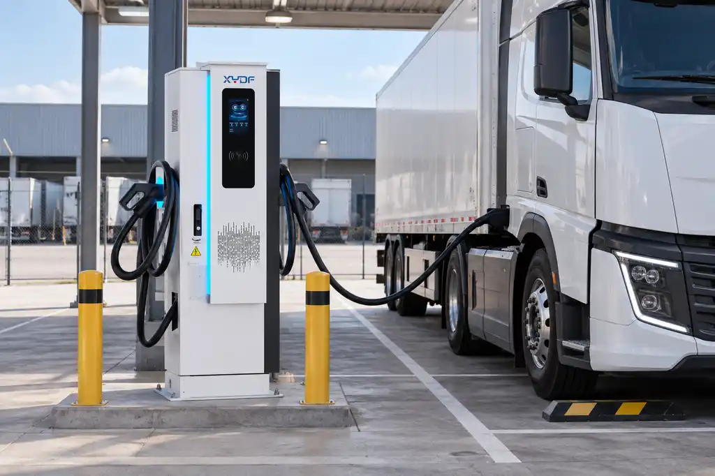
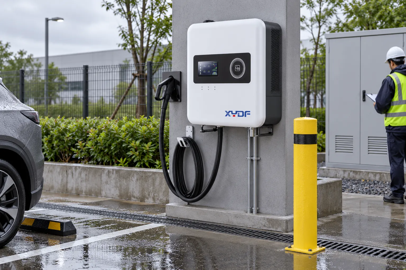
XYDF supplies AC EV chargers, DC fast chargers and commercial charging stations through its EV charger product catalogue. Buyers can compare the Диапазон зарядных устройств AC, the Спектр зарядных устройств DC and the documented 150 kW charging station page, then ask for model-specific installation and protection information for the intended market. Product pages do not replace the site’s electrical design or commissioning tests.
Часто задаваемые вопросы
Do commercial EV charging stations need surge protection?
In most commercial designs, surge protection is a prudent and often code- or specification-driven part of the electrical distribution design. The required devices and locations depend on the supply, exposure, local rules and charger instructions. Have the responsible electrical designer document the selection and coordination rather than adding an unverified device after installation.
How does lightning affect EV charging equipment?
A direct or nearby strike can create conducted or induced transients on power, communications and bonding paths. Damage can affect input protection, power electronics, controls, meters or network interfaces even when the charger is not struck. A layered lightning-protection and SPD design limits the energy and potential difference that reach those circuits.
What type of surge protective device is used for an EV charger?
The device is selected for the system voltage, earthing arrangement, exposure, fault level and location in the distribution hierarchy. Projects may use service-entrance and downstream SPDs, with charger-integrated protection where specified; classifications such as Type 1 or Type 2 must be tied to the applicable regional standard. Confirm the manufacturer’s data sheet, backup protection and coordination requirements.
How should an EV charging station be grounded?
Connect the charger protective-earth terminal to the site’s grounding and bonding system using the conductor and termination method required by the governing code. Bond associated metalwork and coordinate any lightning-protection conductors so fault and transient currents have an intentional path. Test continuity and other prescribed values; do not judge the installation from an isolated rod or one resistance reading.
Where should surge protection be installed in an EV charging system?
Start at the service entrance and add coordinated protection closer to the charger when feeder length, exposure or the equipment design warrants it. Protect external communications circuits or change their routing when they cross the protected boundary. The approved drawing should show each SPD, its bonding point, backup device and conductor route.
How can a site owner inspect surge and lightning protection before commissioning?
Review the approved risk assessment and single-line diagram, confirm SPD ratings and status indicators, inspect bonding and cable routing, and obtain the required continuity and commissioning records. Check that the charger manual and local code have been used together. After a storm, look for SPD status changes, alarms, tripped devices, physical damage and unexplained communication faults; isolate and investigate before resetting repeatedly.
Ссылки
- IEC 62305 series: Protection against lightning, IEC Webstore.
- IEC 61851-1: Electric vehicle conductive charging system, general requirements, IEC Webstore.
- NFPA 780: Standard for the Installation of Lightning Protection Systems, National Fire Protection Association.
- Surge Protective Devices standards resources, National Electrical Manufacturers Association.
Conclusion: protection is a site decision, not a label on the charger
A commercial station is best protected when the project team starts with the site’s exposure and earthing arrangement, follows the transient path from the utility service to the charger, and then selects coordinated SPDs and bonding details that match the governing standard. The sequence matters: confirm the design basis, document the device ratings and locations, test the grounding and bonding, and retain an inspection process for storms and SPD replacement. “Lightning-proof” is not a substitute for those records. XYDF can provide model-specific AC, DC and commercial charging equipment information for a design review; for product selection or project documentation, use the XYDF contact page to request the information needed for the destination market and site conditions.