 Синьцзя Дунфан Электрик Технолоджи Ко., Лтд.



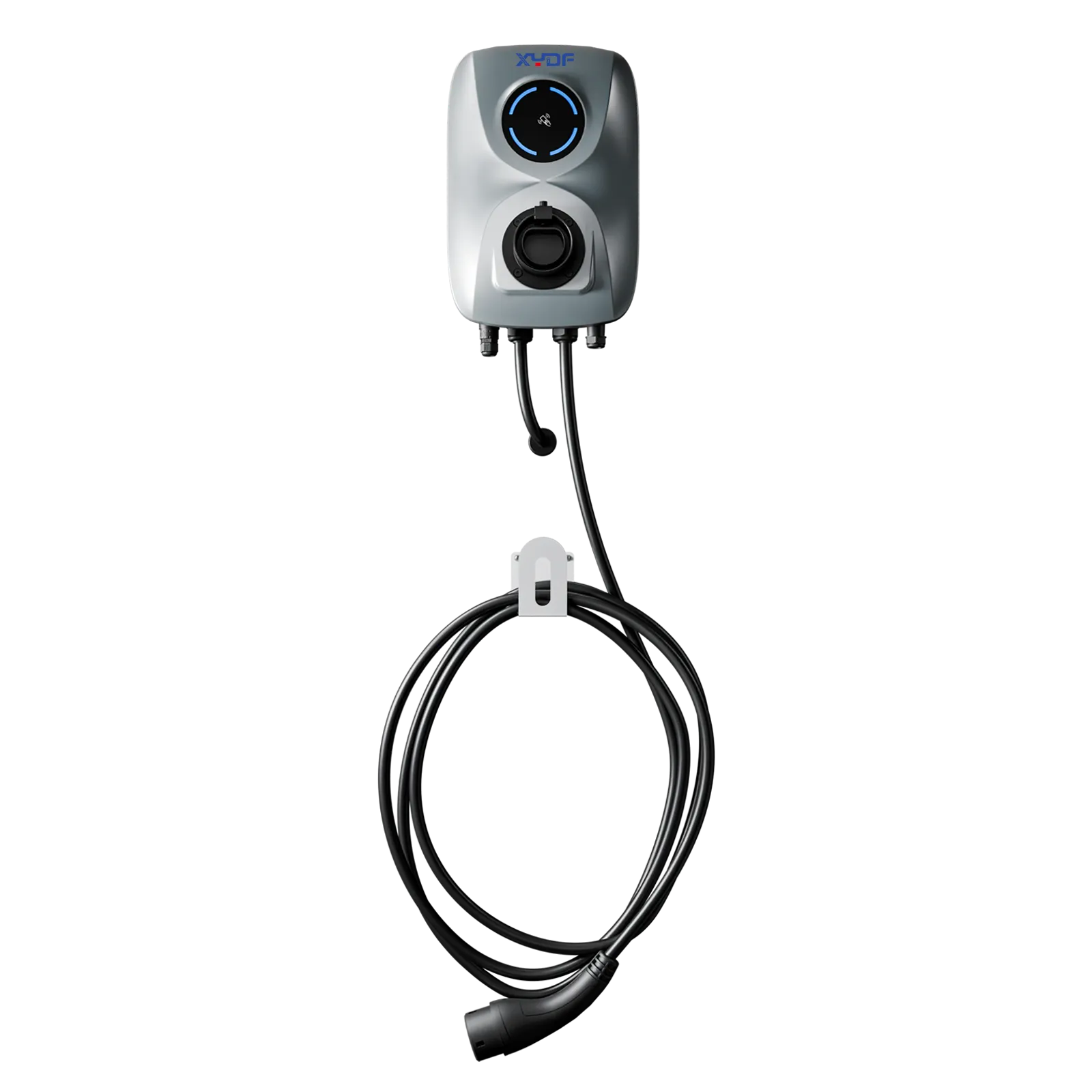


When Mei Lin, an operations manager in Shenzhen, moved 42 delivery vans onto an overnight depot schedule, she approved twelve 60 kW chargers after a vendor compared nameplate power. At 06:30, six vehicles were still below their dispatch threshold, the site’s transformer protection had tripped twice, and drivers queued at the gate. The rapid failure looked like a charger problem. A route-and-dwell review reversed that diagnosis: vehicles arrived in three waves, the utility had limited spare capacity, and most vans needed a lower but longer managed charge. The fix combined a transformer study, 22 kW AC for predictable overnight dwell, four high-power DC points for exceptions, and a dispatch-linked charging policy.
Резюме: A dependable fleet ev charging solution starts with routes, shifts and dwell windows—not a charger count. Map energy per duty cycle, verify depot capacity and transformer headroom, then match AC and DC power to the vehicles that actually need it. Use ISO 15118-ready communications where useful, OCPP for operations, and IEC 61851-1/IEC 62196 as scope references; these standards do not automatically mean a product is certified. A staged pilot with acceptance tests, load balancing and a measured uptime baseline generally reduces capital risk more effectively than buying the highest-rated hardware first.
Fleet electrification is now an operating-model decision. A logistics company protects delivery cut-off times; a transit agency protects headways; a taxi operator protects driver earning time. The charging yard is therefore part of the fleet’s production system, connected to telematics, electricity tariffs, maintenance and contingency planning. This guide sets out a repeatable method for depots, logistics, commercial, municipal and specialty fleets.
1. Start with duty cycles: four fleet scenarios, four design priorities
Begin with a 30-day sample of vehicle departures, returns, state of charge (SoC), payload, weather and route distance. Convert each duty cycle into energy required at the battery, add a documented reserve, and record the minimum dwell time. A useful first-pass equation is: required charging energy = (route kWh × reserve factor) − energy remaining on arrival. Use measured telematics where available; illustrative assumptions should be labelled, not presented as field facts.
Logistics and last-mile delivery
Vans and rigid trucks often return to one depot, but arrival times vary with traffic and loading. Separate “must leave” vehicles from flexible vehicles, and reserve DC power for late returns or a second shift. A practical fleet depot charging and shift scheduling model ranks vehicles by departure deadline, minimum SoC and route criticality. For heavier regional routes, review the logistics fleet EV charging station specification for cable reach, wheel stops, weather exposure and traffic segregation.
Bus and transit operations
Transit fleets have timetable constraints that can make a short opportunity charge more valuable than a large overnight window. Compare depot pantograph or plug-in charging with on-route opportunity points, and model layover variability. The design must protect pull-out times, accessibility clearances and safe pedestrian movement; a charger that works in a laboratory can fail operationally if buses cannot align consistently.
Taxi and ride-hail fleets
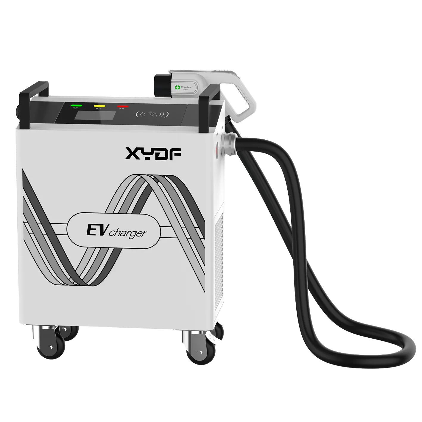
High utilization and short stops favour fast DC, but demand charges and connector queues can erase the apparent benefit. Measure charging events per shift, average stop duration and the percentage of drivers who can charge at home. A shared hub with reservation and fair-queue rules may outperform a private charger for every vehicle, while a mobile unit can cover a temporary event or recovery need; see the mobile EV charger solution for fleet operators discussion.
Municipal and specialty fleets
Police, refuse, utility, mining and emergency vehicles have irregular, high-consequence duty cycles. Keep a defined emergency reserve and design physical redundancy so one failed dispenser does not ground the whole capability. The CRRC mining vehicle charging station case illustrates why vehicle mass, harsh environments and controlled access should be treated as first-order design variables, not footnotes.
2. Translate routes and dwell into a power architecture
Build a route/shift matrix with five columns: vehicle class, daily kWh, return SoC, available dwell and departure deadline. Add a sixth column for “opportunity if missed.” This reveals whether power is constrained by energy, time, or simultaneous arrivals. For example, 30 vans each needing 35 kWh over a 10-hour window have a modest average load, yet a two-hour arrival wave can create a high peak unless charging is sequenced.
Fleet depot charging should be sized for the worst credible operating day, not an extreme theoretical event. Define a service-level target such as “95% of scheduled departures above the agreed SoC,” then test the design against missed returns, cold weather and a failed charger. Keep the target contractual and measurable; avoid unsupported uptime guarantees.
Depot electrical capacity and transformer planning
Request a utility load letter, one-line diagram and interval data before selecting chargers. Confirm service voltage, spare transformer capacity, short-circuit rating, protection coordination, cable routes, earthing and future expansion space. A 400 V AC distribution system is common for many depots; 800 V vehicle platforms can reduce current for a given power but require compatible insulation, contactors and charging equipment. Voltage alone does not predict charge speed—the vehicle’s battery voltage, current limit and thermal state do.
Plan the transformer and switchgear as a lifecycle asset. Include harmonic assessment where power electronics are concentrated, power-factor assumptions, ventilation, flood level, fire separation and access for maintenance. Obtain the utility’s interconnection approval before civil works. If a site cannot support the desired peak, options include staged energization, on-site storage, a second service, or a lower-power overnight profile; each has different permitting and operating implications.
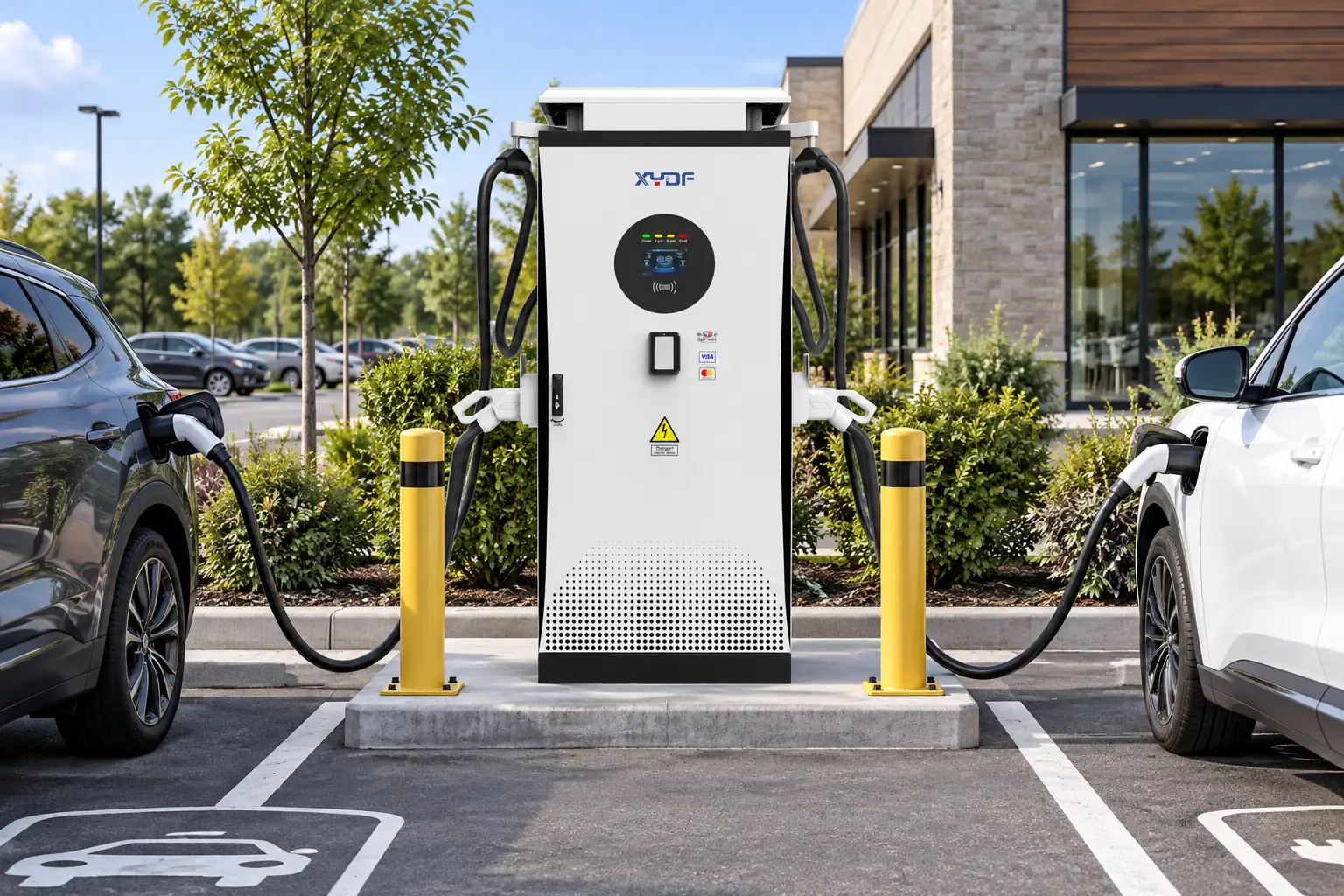
Do not overlook the parking geometry around that electrical design. Draw the turning radius of the longest vehicle, reversing movements, trailer swing and pedestrian desire lines. Put dispensers where a driver can connect without crossing an active lane, and leave enough slack for a connector on either side when vehicle inlets differ. Bollards, wheel stops, drainage and snow or wash-down routes protect equipment; lighting and visible emergency signage reduce response time. For buses and refuse vehicles, confirm that mirrors, lifts and body-mounted equipment cannot strike a cabinet. A lower-rated charger in the right bay can deliver more usable service than a high-rated unit that forces unsafe manoeuvres.
AC versus DC: assign jobs, not labels
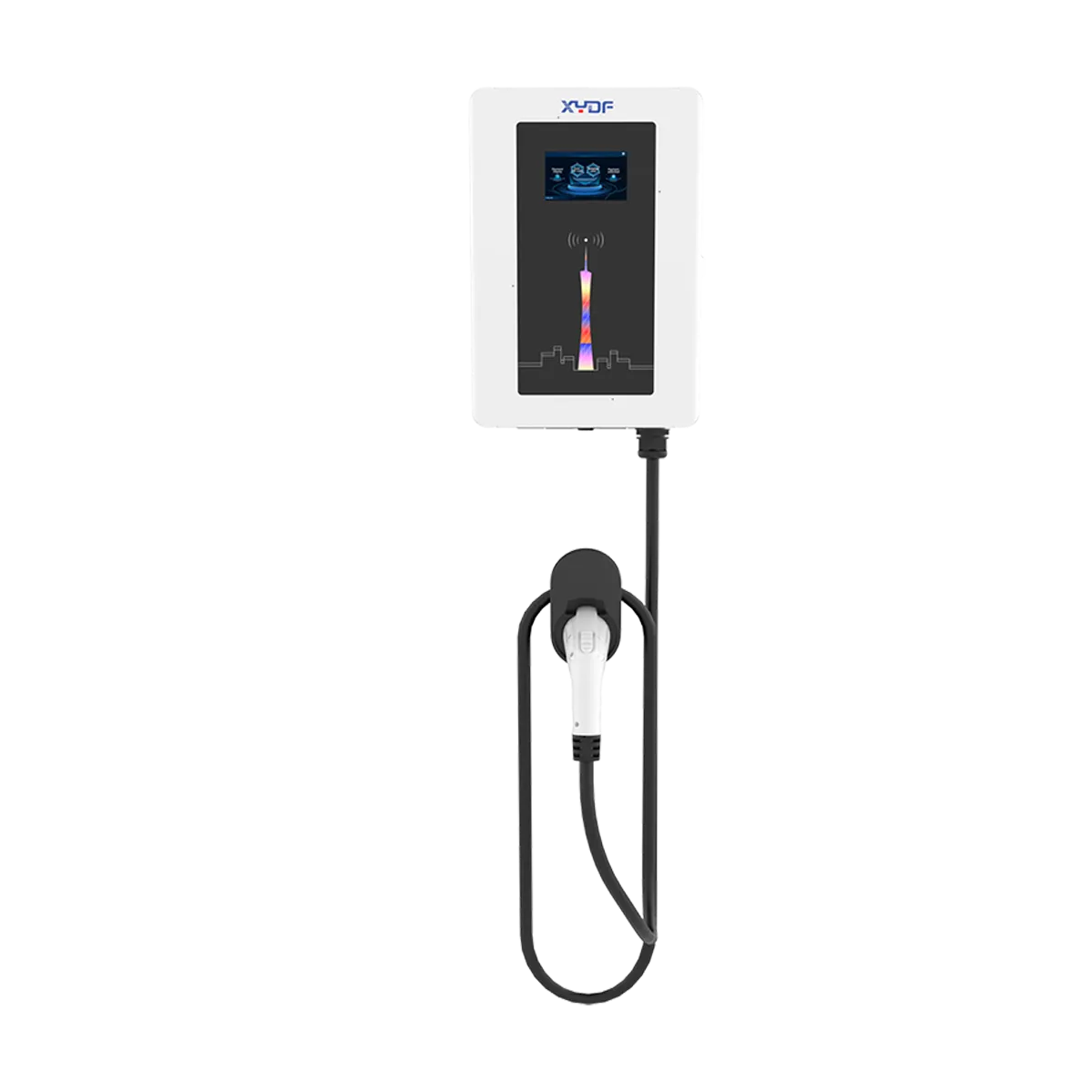
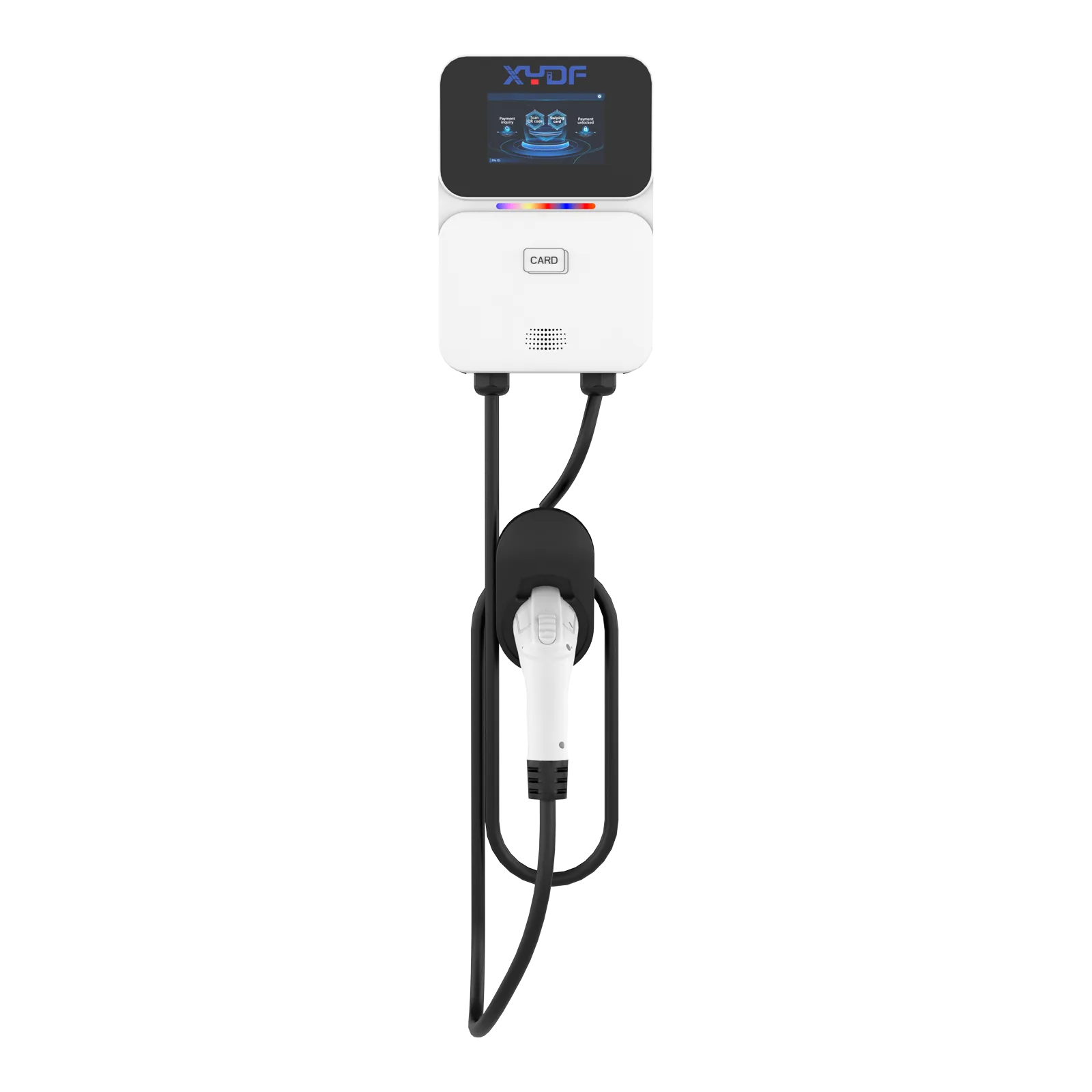
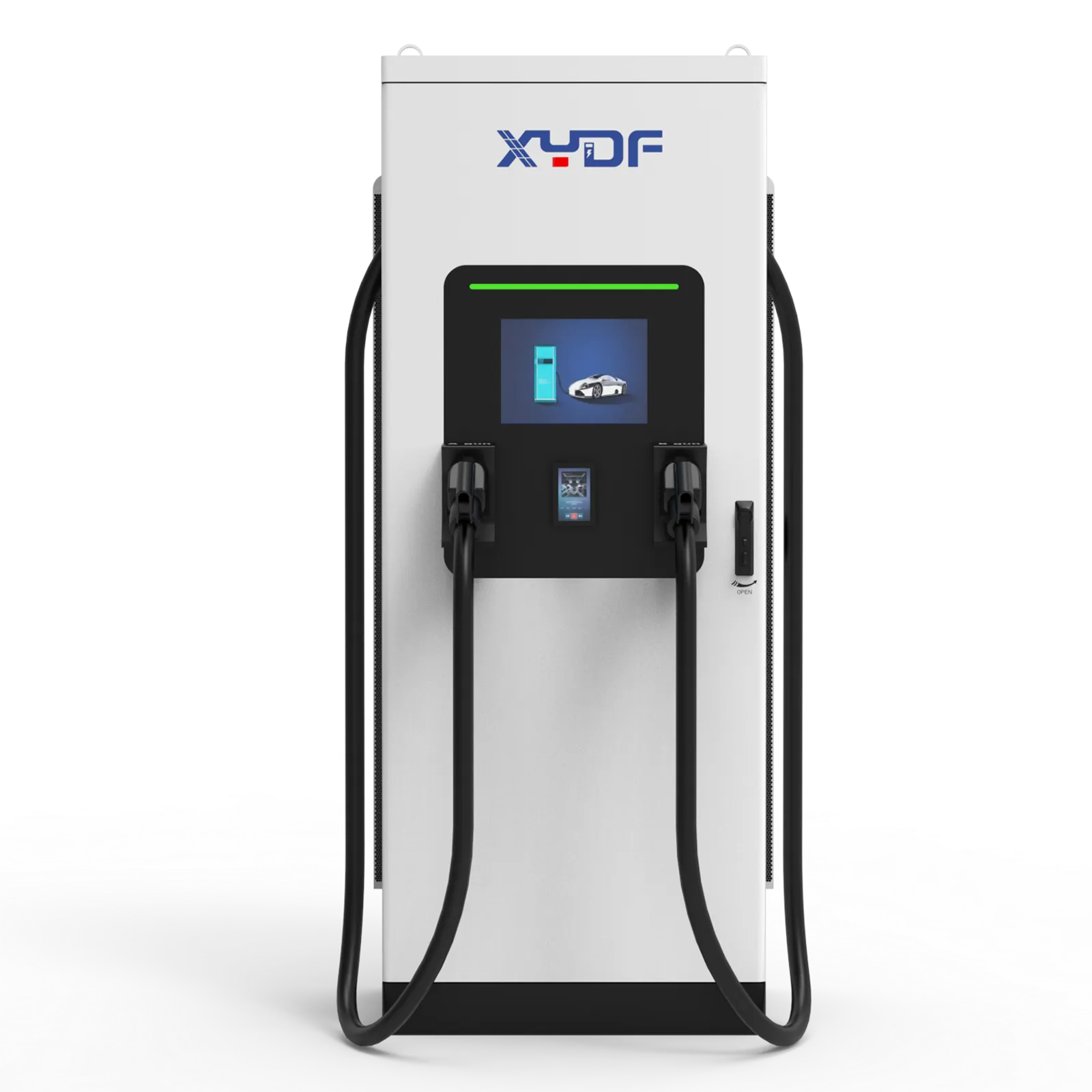
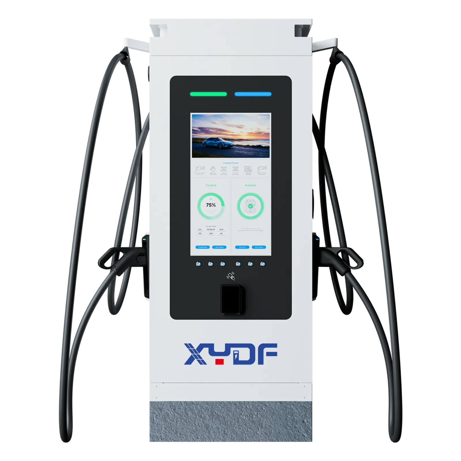
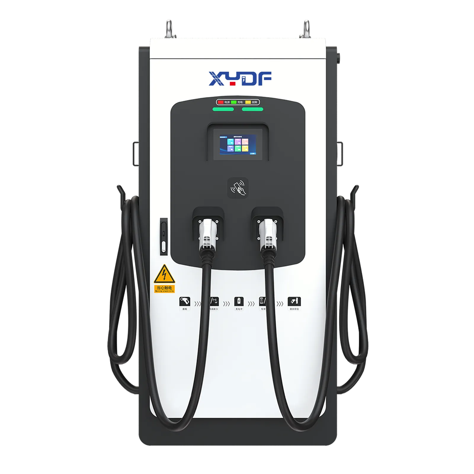
AC charging is often efficient for long, predictable dwell because the vehicle’s onboard charger controls conversion. DC charging is useful when the vehicle must leave soon, has a large battery, or returns late. Compare delivered energy, not just rated kilowatts: a 22 kW AC point used for eight hours can deliver more scheduled energy than a 120 kW DC point throttled by a congested feeder. Confirm cable length, connector lock, ingress protection, ambient derating and vehicle charge curves.

3. Make the site predictable with managed charging
Unmanaged charging asks every vehicle to start at once; managed charging allocates available power according to deadlines and energy need. The controller should read meter limits, charger status and vehicle SoC, then adjust setpoints without violating vehicle or equipment limits. Use a documented priority hierarchy: safety-critical vehicles first, then fixed departure times, then route energy, then cost optimization.
Load balancing and tariff control
Fleet charging infrastructure needs both static and dynamic limits. Static limits protect the contracted connection; dynamic limits respond to building load, solar output, battery state and demand-charge windows. Record every curtailment event so operators can distinguish a deliberate policy from a fault. A 15-minute demand interval is common in utility tariffs, but the actual interval and ratchet rules vary by jurisdiction; model the local tariff rather than copying a generic savings percentage.
Integrate the energy-management system with the charge-point management system (CPMS). OCPP can carry transaction, status and smart-charging messages, while an API can exchange dispatch deadlines with fleet software. ISO 15118 may enable secure identification and managed charging features when both vehicle and charger support the relevant edition; do not promise plug-and-charge simply because a device is “ISO 15118 ready.”
Connector compatibility and mixed fleets
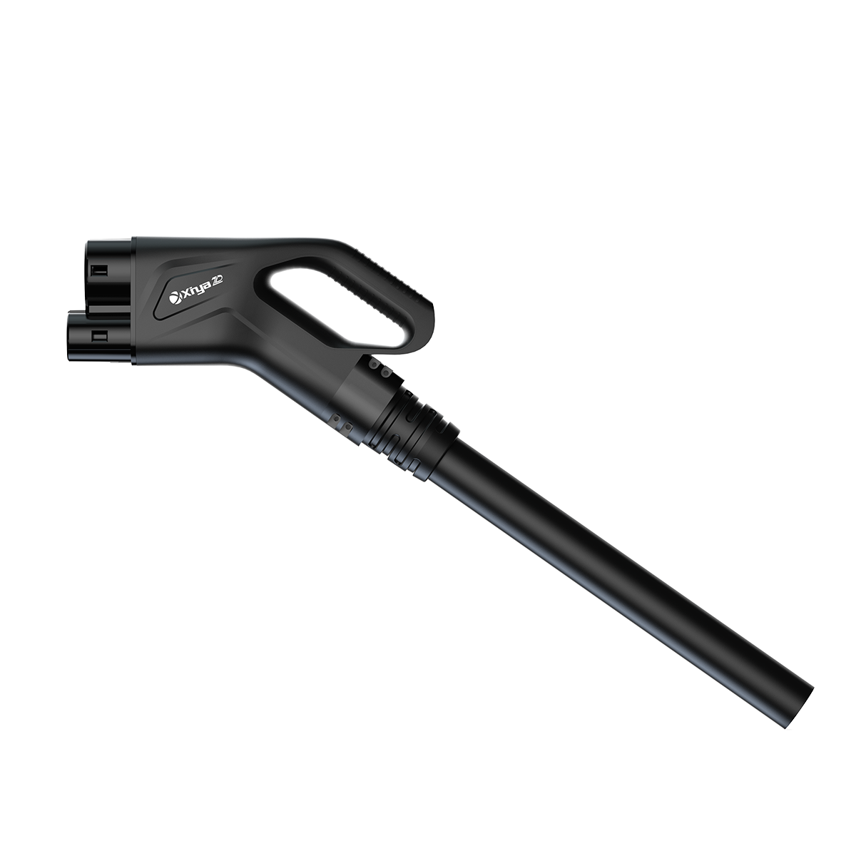
Inventory every inlet: Type 2, CCS1, CCS2, CHAdeMO, GB/T or a proprietary interface, plus auxiliary power needs. Connector adapters can create safety, warranty or metrology questions, so use only approved combinations. For a mixed fleet, run an RFQ that specifies connector count, cable management, authentication, backend data, payment or cost allocation and future vehicle additions. The mixed-fleet connector RFQ checklist can help buyers turn a vague compatibility request into testable requirements.
Uptime, redundancy and maintenance
Define availability as a measurable denominator: for example, the percentage of scheduled charging sessions that can start and deliver energy during agreed hours. Track failed starts, derating, communication loss, payment/authentication errors and mean time to repair separately. Redundancy can mean spare dispensers, dual connectors, bypass power paths or a mobile backup—not merely a second brand of charger.
Specify preventive maintenance: visual inspection, connector and cable checks, thermal scans, residual-current protection tests, firmware governance and cleaning. Keep critical spares on site where lead times justify them, and require remote diagnostics with role-based access. The five factors for a fleet charging project are a useful governance prompt: site, vehicles, power, operations and support should be signed off by different owners.
4. Compare architecture options with total cost of ownership
Capital cost is only one line in a fleet business case. Include utility upgrades, civil works, design and permitting, software subscriptions, networking, electricity, demand charges, maintenance labour, downtime, battery degradation assumptions and eventual replacement. Assign costs to a vehicle or route so finance can compare charging with fuel and with outsourced public charging.
| Архитектура | Лучший вариант | Operational strengths | Предостережения | Водители TCO |
|---|---|---|---|---|
| Predominantly AC depot | Predictable overnight dwell | Lower peak load; simple sequencing; many parking bays | Needs enough dwell; slower recovery after missed returns | Number of bays, trenching, demand tariff, onboard charger limits |
| DC hub with managed queues | High utilization, short dwell, mixed arrival times | Fast recovery; shared dispensers can serve more vehicles | Higher connection and cooling requirements; queue risk | Transformer, demand charges, utilization, service contract |
| Hybrid AC/DC depot | Most logistics and municipal fleets | Routine charging is economical; exceptions get speed | More complex controls and spares | Controller integration, power allocation, layout efficiency |
| On-route opportunity | Transit with repeatable layovers | Smaller onboard batteries; supports long duty cycles | Permitting, roadside access and weather exposure | Grid connection, civil works, site lease, service access |
| Mobile or temporary DC | Events, construction, emergency cover | Flexible deployment; useful during civil delays | Limited throughput; logistics and safety coordination | Rental/transport, fuel or battery recharge, staffing |
Use a scenario model with at least three cases: normal day, constrained-grid day and growth case. For each, calculate energy delivered, peak kW, sessions completed, vehicles missing target SoC and cost per delivered kWh. Label all assumptions—especially electricity price, demand tariff, utilization and battery replacement—so the model can be audited.
Operational data, people and cyber resilience
A technically sound fleet ev charging solution still fails if the operating data is late, incomplete or owned by nobody. Assign a data owner for vehicle telemetry, a site owner for electrical alarms and a dispatch owner for departure priorities. Define the minimum event record—vehicle ID, connector, start and stop time, energy, SoC when available, target departure, interruption reason and meter identifier. Keep timestamps synchronized across the vehicle, charger and CPMS so a missed session can be reconstructed.
Design the human workflow before the dashboard. Drivers need a simple bay map, plug-in confirmation and a clear escalation route; dispatchers need to see which vehicles are at risk, not a page of raw alarms; technicians need safe isolation instructions and parts information. Train contractors on emergency stops, damaged cables, water ingress and incident reporting. Review the procedure after the first two weeks of operation, when real behaviours usually expose queueing or cable-reach problems.
Cybersecurity is part of uptime. Separate charger traffic from office networks, use unique credentials and role-based permissions, and document how certificates and firmware are renewed. Require vendors to disclose supported TLS versions, logging, vulnerability notification and end-of-life policy. Test a network outage: local charging should follow a safe fallback schedule, while queued transactions and meter data should reconcile when communications return. Do not connect a charger to a fleet-control API until ownership, authentication and data minimization are agreed.
Energy and vehicle data also has commercial sensitivity. A depot’s load profile can reveal production volumes, while location history can expose public-service patterns. Retain only what the contract and law require, restrict exports, and set a deletion or anonymization schedule. If a third-party CPMS is used, clarify who owns raw meter data and who can access it after contract termination. These controls protect the business case as much as the equipment.
Acceptance metrics that operators can act on
At handover, publish a one-page scorecard. Include scheduled sessions, successful starts, energy delivered versus target, peak site kW, demand-window events, charger faults by code, mean time to acknowledge, mean time to restore, and departures below target SoC. Set a review cadence—daily during pilot, weekly during ramp-up, monthly after stabilization. A falling success rate with normal power availability points to connectors, authentication or workflow; a rising peak with normal sessions points to policy or tariff configuration.
Use a controlled change process for firmware, tariffs and priority rules. Record the old and new setting, approver, test evidence and rollback method. When vehicles are added, update the connector matrix and route simulation before assigning them to live bays. This discipline prevents “small” changes from creating a fleet-wide charging queue.
Phased rollout and acceptance gates
Phase zero is feasibility: confirm routes, utility capacity, planning permission, fire review and procurement lead times. Phase one is a representative pilot with a limited number of vehicles and a complete data trail. Phase two expands bays and power only after the pilot meets its service-level targets through at least one peak operating week. Phase three optimizes tariffs, storage or on-route charging once the baseline is stable. At every gate, keep a fallback location or contracted public charging allowance for critical work.
Document what happens when the site is late. If a utility upgrade slips, install conduits and foundations first, operate a lower-power temporary profile, or use a mobile unit for defined exceptions. If a vehicle delivery slips, do not oversize the entire electrical system without a trigger; preserve expansion space and release capital against confirmed duty cycles. A clear decision log keeps the project aligned across fleet, facilities, finance and procurement teams.
5. Expand the design by fleet dimension
| Измерение | Вопросы для ответов | Design implication | Доказательства для запроса |
|---|---|---|---|
| Duty cycle | What are daily kWh, return SoC and missed-departure consequences? | Set power, reserve and priority rules by route | Telematics export, dispatch plan, cold-weather sample |
| Модель обитания | Are returns clustered, staggered or unpredictable? | Choose bay count, queue logic and DC exception capacity | Arrival histogram, loading schedule, gate plan |
| Grid and space | What service, transformer and civil constraints exist? | Stage switchgear, conduits and future expansion | Utility letter, one-line, soil/drainage and fire review |
| Состав транспортных средств | Which connectors, voltages and charge curves are present? | Provide compatible outlets and power sharing | OEM manuals, inlet photos, warranty conditions |
| Operating resilience | What happens during charger, network or utility failure? | Keep spares, manual override and fallback locations | Incident playbook, SLA, test records |
| Financial control | Who pays, and how are energy and demand costs allocated? | Metering, tariff windows and cost-centre reporting | Tariff sheet, finance model, submeter architecture |
6. Standards, compliance and acceptance
Use standards as a specification and test framework, then verify local legal requirements. IEC 61851-1 addresses conductive charging system safety and control principles. IEC 62196 covers plugs, socket-outlets, vehicle connectors and vehicle inlets. ISO 15118 defines vehicle-to-grid communication layers and related functions. OCPP, maintained by the Open Charge Alliance, supports interoperability between charge points and management systems but is not itself a safety certification.
IEC 62477-1 provides safety requirements for power electronic converter systems and can inform equipment and installation reviews. Add the destination market’s electrical code, grid interconnection rules, fire protection, accessibility, construction, data-privacy, cybersecurity, payment and metrology requirements. A reference to a standard is not proof of certification, listing or legal approval; ask for the exact certificate scope, issuing body, model number and validity where a claim matters.
Write acceptance tests before equipment arrives. Test insulation and protective earth, residual-current response, emergency stop, connector lock, pilot/control signals, meter accuracy, communications loss, firmware rollback, load shedding, cold or hot derating and recovery after a power cycle. Run a live fleet simulation with the actual CPMS and dispatch priorities. Record serial numbers, calibration status and as-built drawings in the handover pack.
7. A practical selection and rollout guide
- Baseline the duty cycle. Export four to eight weeks of route, SoC and arrival data; interview dispatchers and drivers about exceptions that telematics misses.
- Secure the grid path. Obtain utility feasibility, transformer and protection studies, then reserve conduits and switchboard space for the growth case.
- Specify the operating system. Require OCPP version and profiles, user roles, API access, data retention, alarm routing and a manual fallback. Define availability metrics and response times without inventing guarantees.
- Pilot one representative block. Include the hardest route, mixed connectors and a constrained-load day. Run acceptance tests for at least one complete dispatch cycle.
- Scale by gates. Release the next phase only when energy delivered, peak demand, failed starts, repair time and departure SoC meet the agreed thresholds.
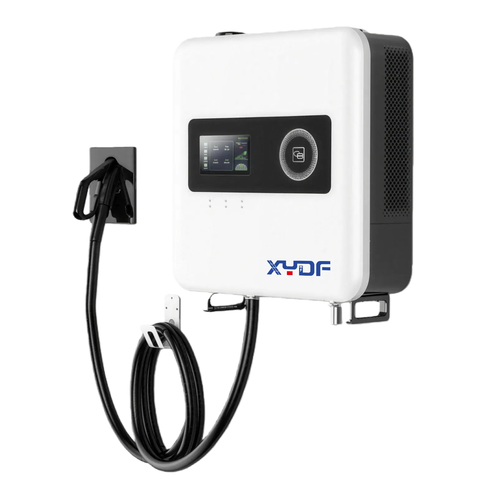
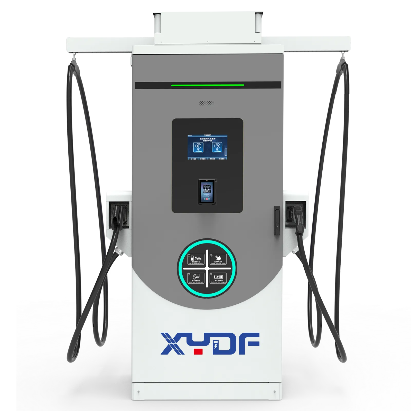
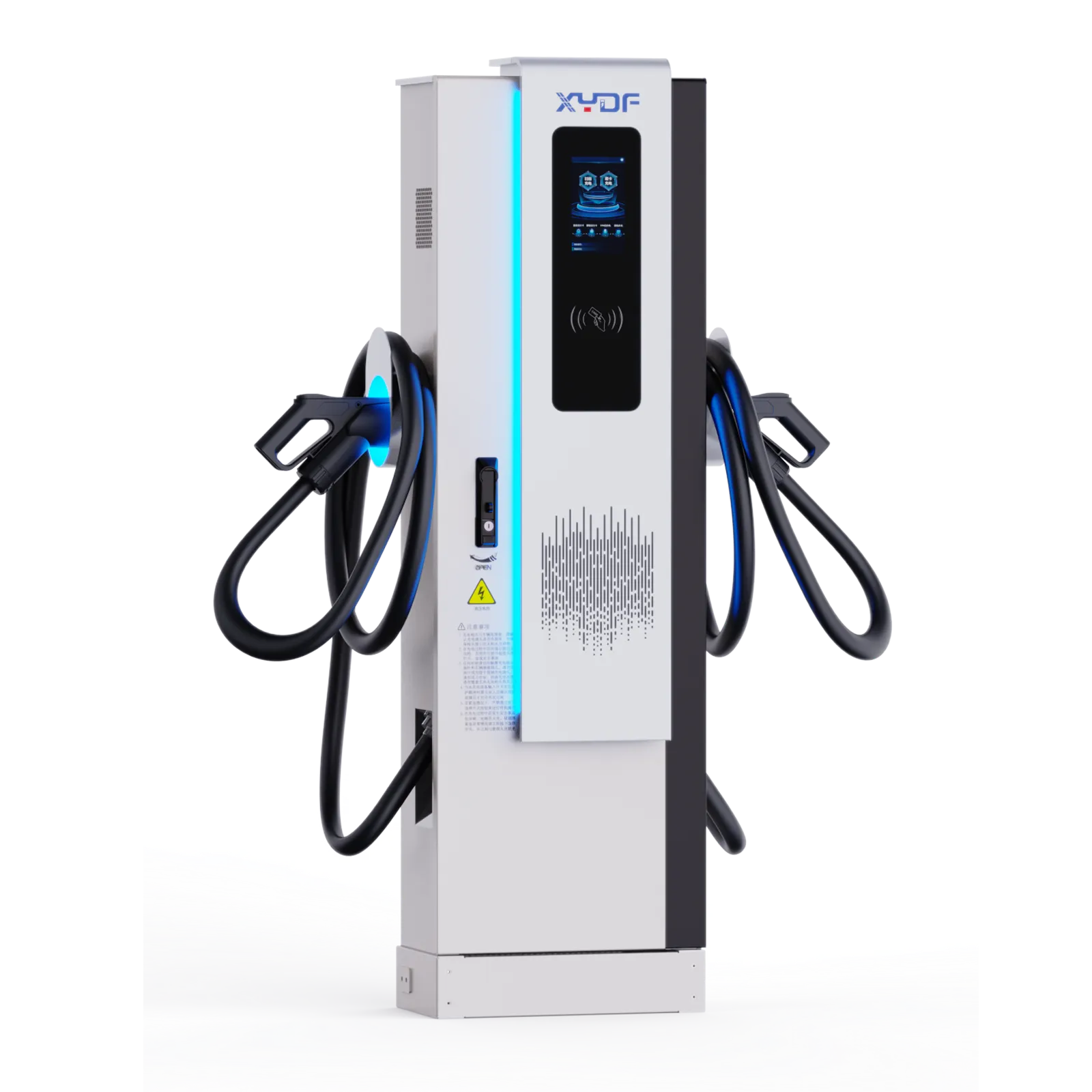
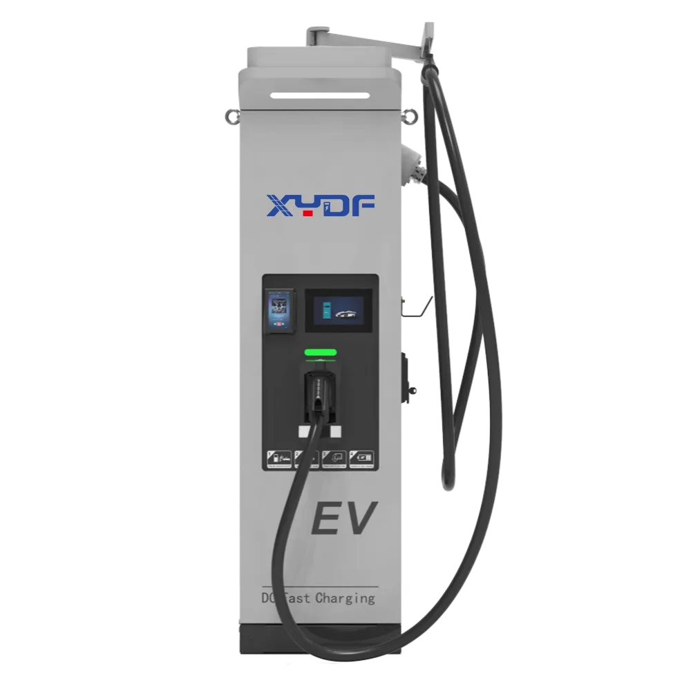
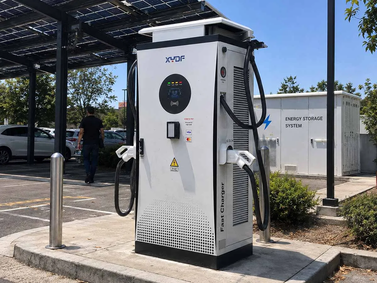
XYDF (Xinya EE) can be considered during the sourcing stage when a buyer needs configurable AC/DC equipment, site documentation and coordination across vehicle, electrical and software suppliers. Evaluate any supplier against the same drawings, test plan, service coverage and evidence requirements; product fit and support process matter more than a broad catalogue claim. For scalable options, compare architectures in the best scalable EV charging options for fleets руководство.
Rollout should be phased: feasibility and design, pilot installation, controlled expansion, then optimization. Include driver training, bay markings, cable handling, winter or heat procedures, and a change-control owner. Large multi-site programs need a common data model and a local escalation path. The Chery dealership charging program shows why repeatable documentation and site-by-site commissioning discipline become decisive at scale. For public-sector governance and traffic-critical operations, review the Nanjing traffic police detachment charging station case as a context reference, not a promise that every site has identical conditions.
Часто задаваемые вопросы
What is the most important input for a fleet charging plan?
Reliable duty-cycle data is the foundation: route energy, return SoC, dwell and departure deadlines. If data is incomplete, instrument a representative sample and document assumptions before buying hardware. Revisit the plan after the first pilot month.
Should a depot choose AC or DC chargers?
Choose AC for long, predictable dwell and DC for short or uncertain dwell; a hybrid normally handles both routine and exception charging. Compare delivered energy and peak demand, not rated kW alone. Vehicle charge curves and utility limits can change the answer.
How many chargers does a commercial fleet need?
Calculate bays from simultaneous arrivals, dwell and a failed-unit scenario, then validate with a dispatch simulation. A shared DC dispenser may serve several vehicles, while dedicated AC bays reduce queue movements. The correct number is the smallest set that meets the departure service level with resilience.
Can managed charging reduce electricity cost?
It can shift energy away from expensive demand windows and prevent coincident peaks, subject to tariff rules and vehicle deadlines. Savings are site-specific and should be modelled with interval data. Keep an override for safety-critical or late-return vehicles.
What does OCPP compatibility guarantee?
OCPP can improve interoperability between a charge point and a CPMS, but versions, profiles and vendor implementations differ. Test the exact functions you need—smart charging, alarms, remote reset, firmware and data export—before contract signature. It does not replace electrical, cybersecurity or local compliance checks.
How should fleet uptime be reported?
Define the denominator and window, then separate failed starts, communication faults, power derating and repair time. Report scheduled sessions that could start and deliver energy, alongside missed departures and root cause. This is more useful than a single unqualified percentage.
Ссылки
- Международная электротехническая комиссия (IEC), IEC 61851-1, IEC 62196 and IEC 62477-1 scope information.
- ISO 15118 road vehicles communication interface, International Organization for Standardization.
- Open Charge Alliance protocols, OCPP documentation and releases.
- Центр данных по альтернативным топливам Департамента энергетики США, charging infrastructure and fleet planning resources.
- Международное энергетическое агентство, Глобальный прогноз развития электромобильности на 2024 год, market and infrastructure context.
The durable principle is simple: design the charging operation around the vehicle’s work, then make power, software and maintenance serve that schedule. When the evidence supports the next phase, specify a commercial fleet EV charging package or electric fleet charging strategy that can grow without hiding its constraints.
For a project-specific review, compare your route matrix, utility study and acceptance plan with XYDF/Xinya EE’s configurable fleet ev charging solution Варианты быстрой зарядки от DC и Зарядные устройства для электромобилей. Contact the team with your vehicle mix, connector standards, site voltage and target dispatch window so the next design decision is based on measured duty cycles.