 Xinya Dongfang Electricity Technology Co., Ltd.


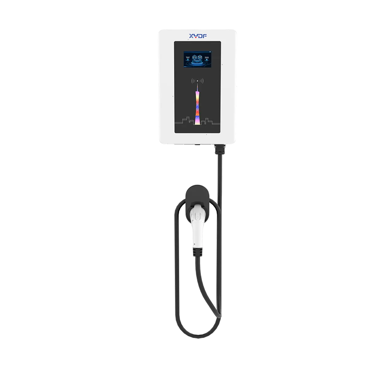
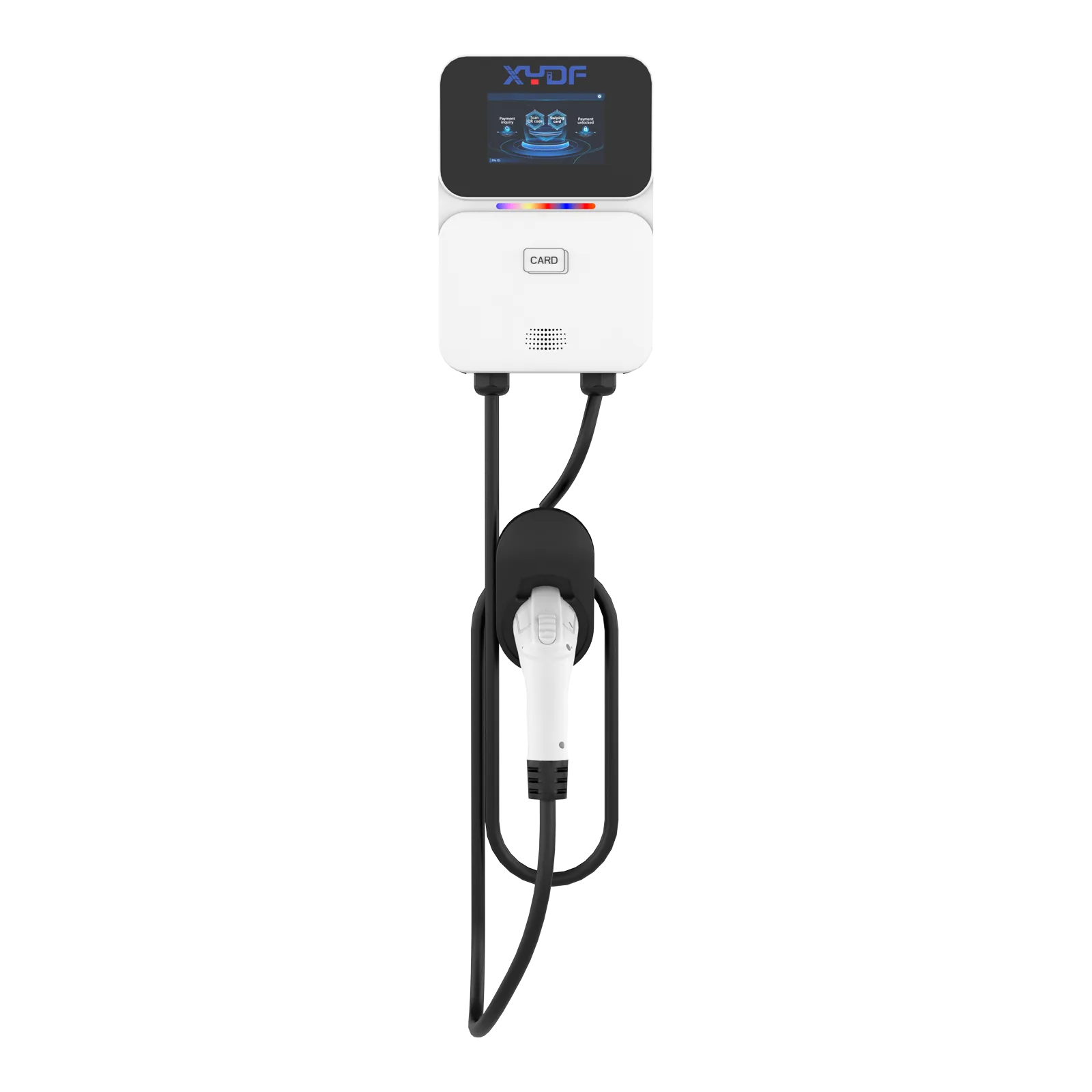
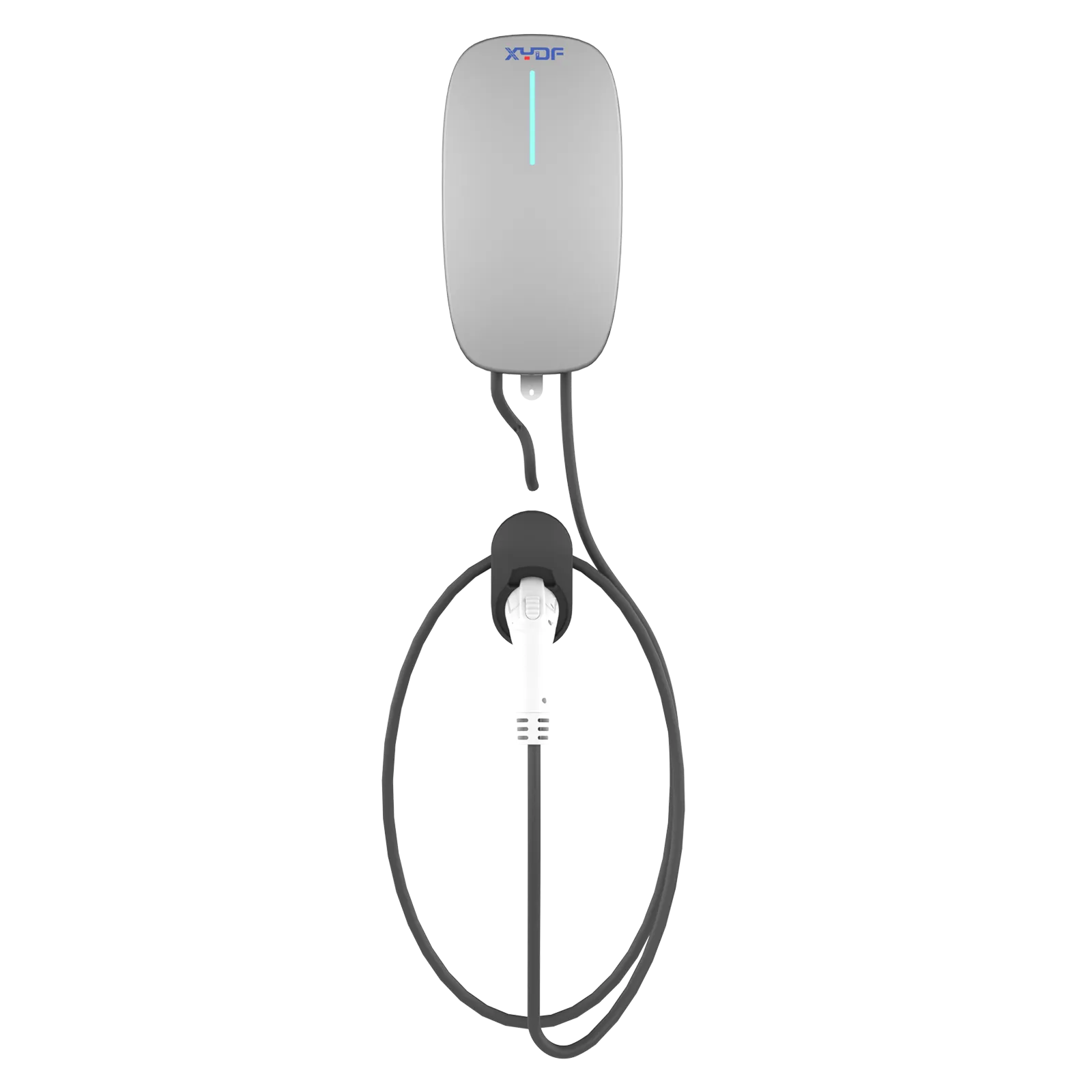
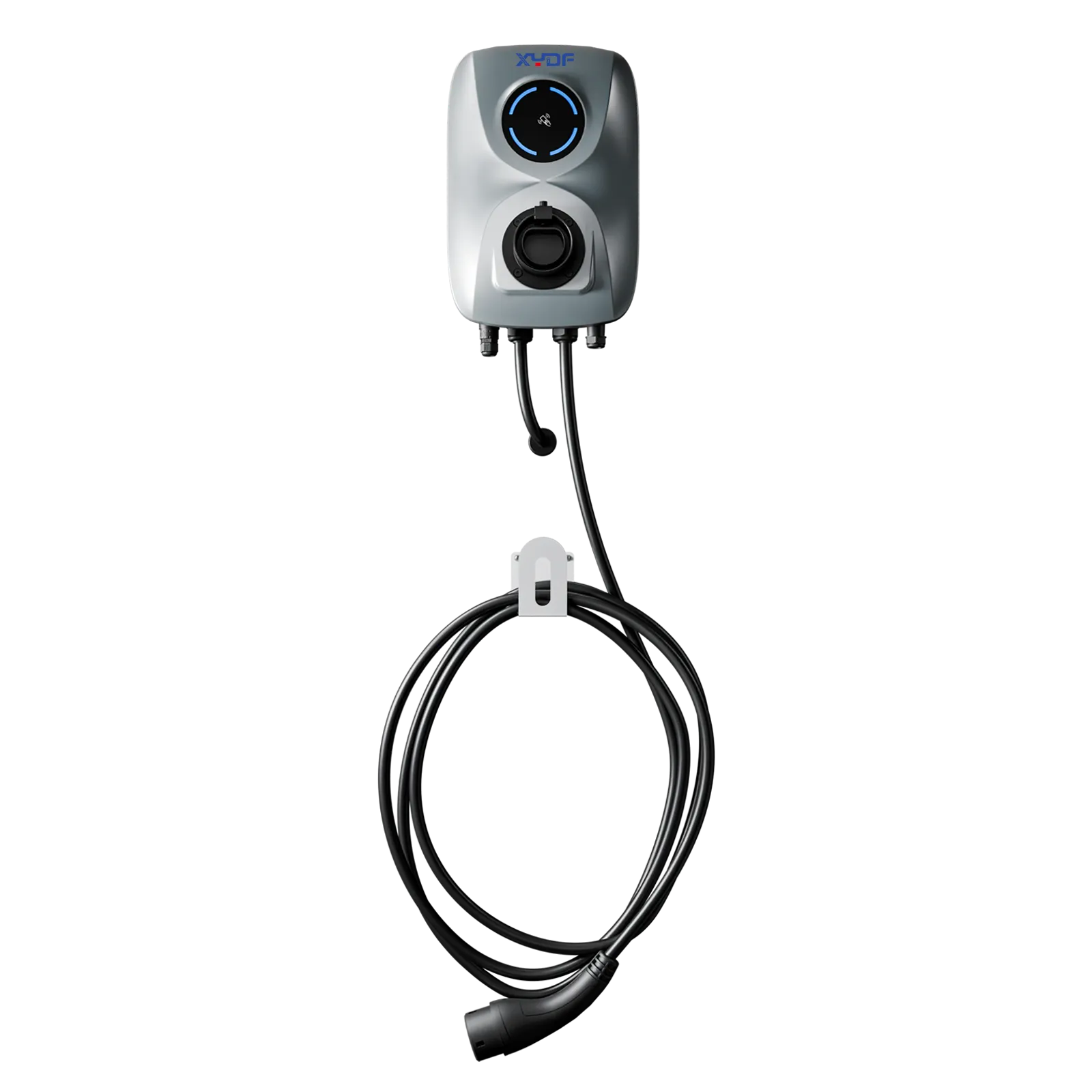
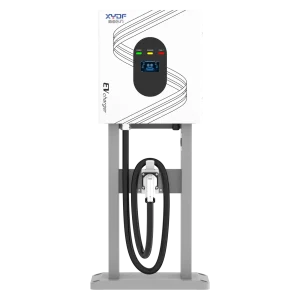

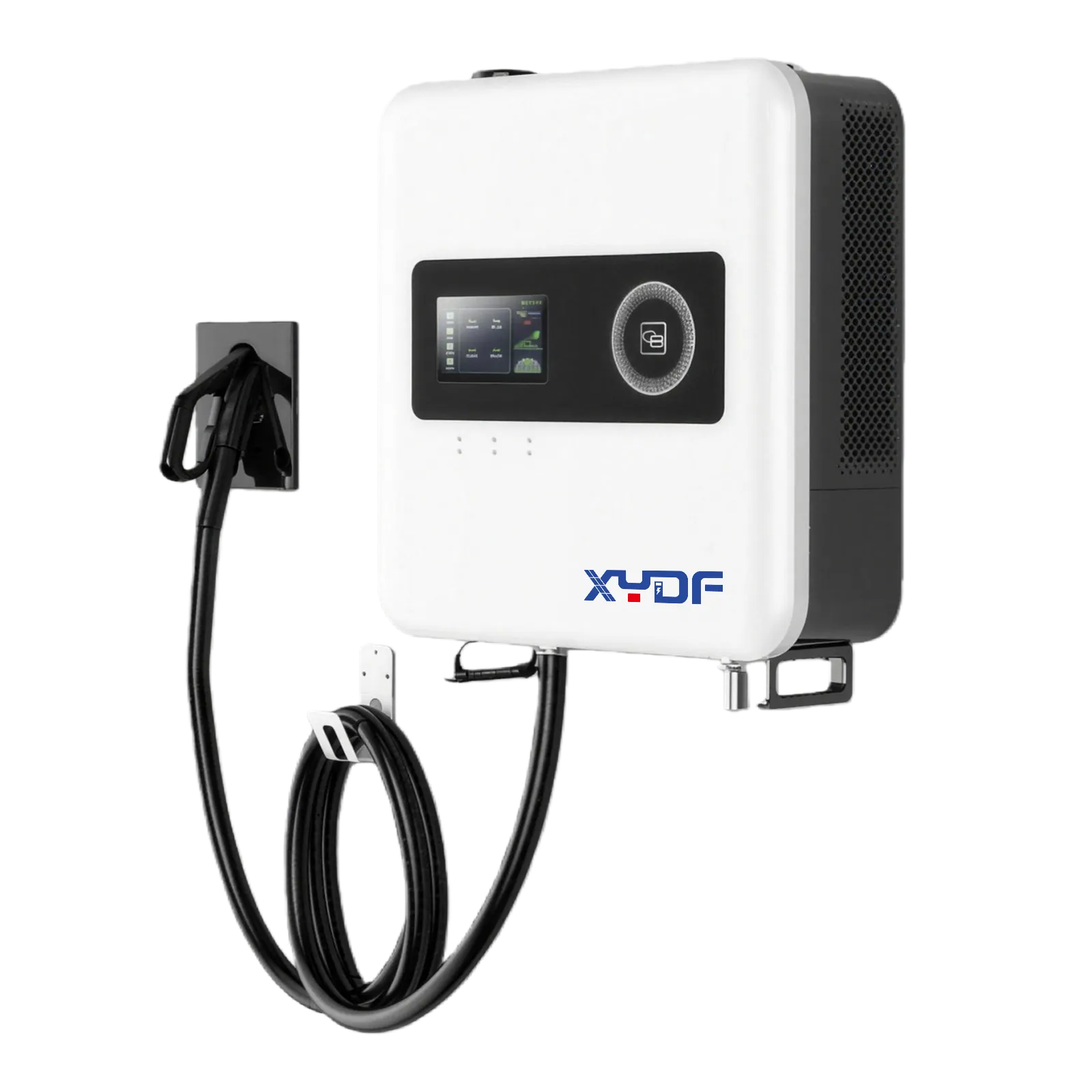
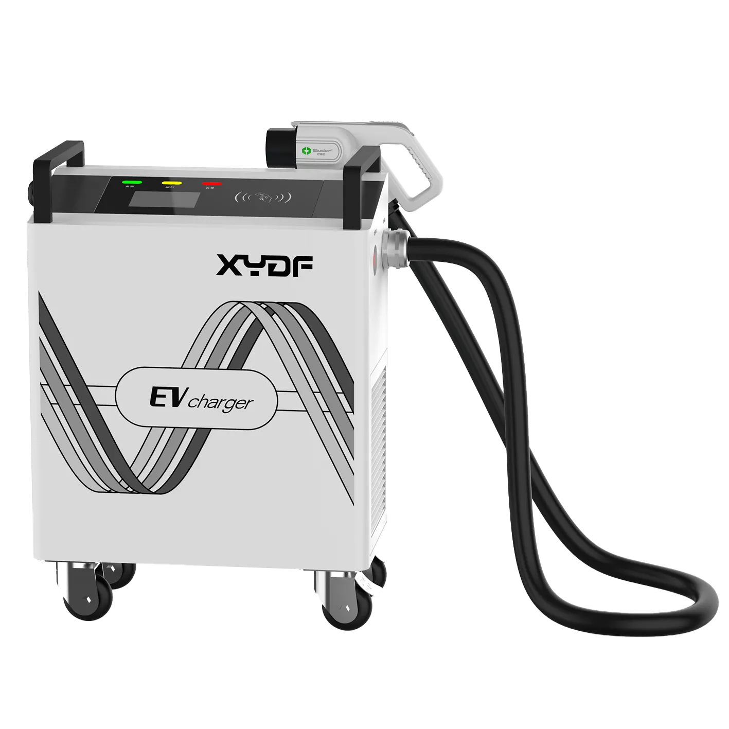
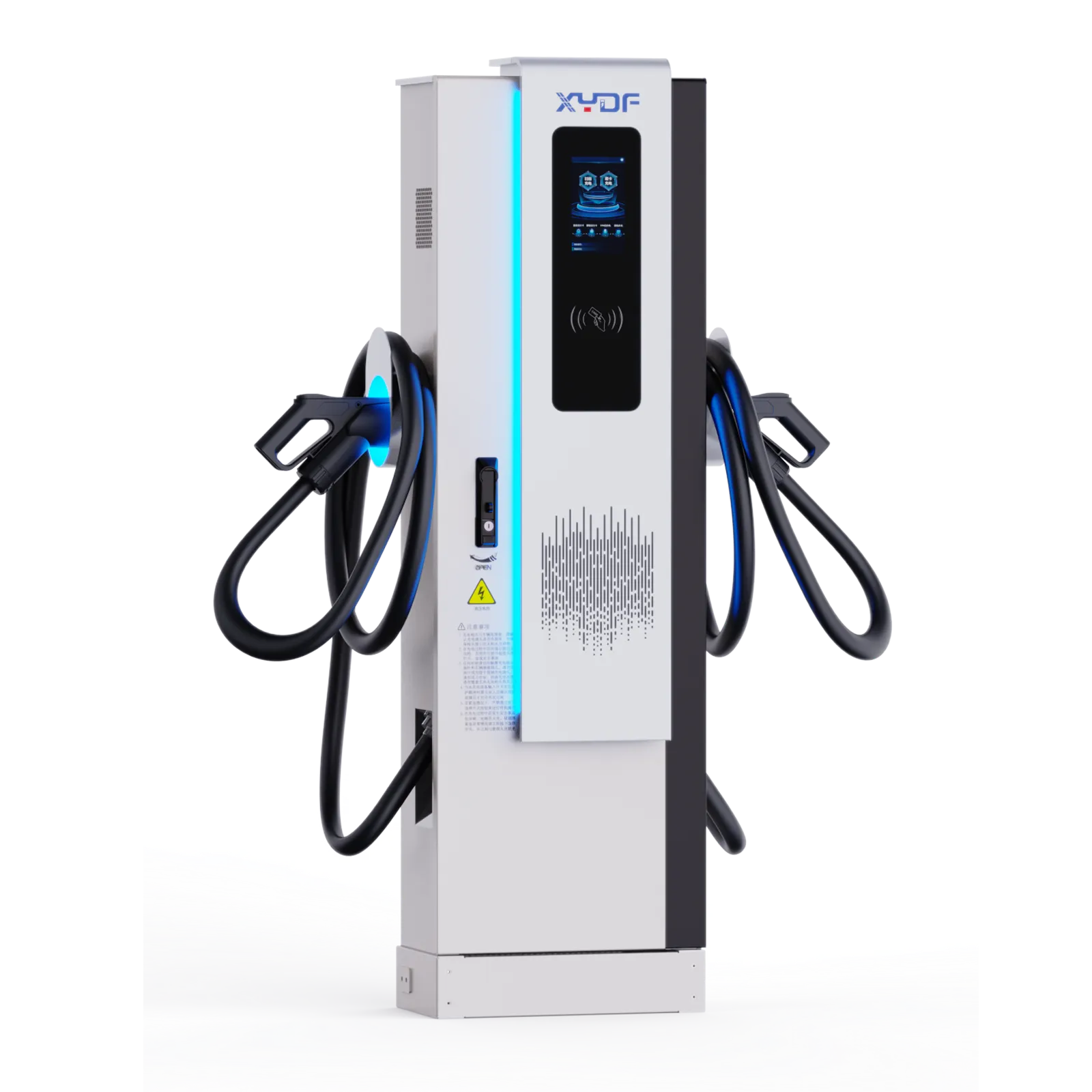
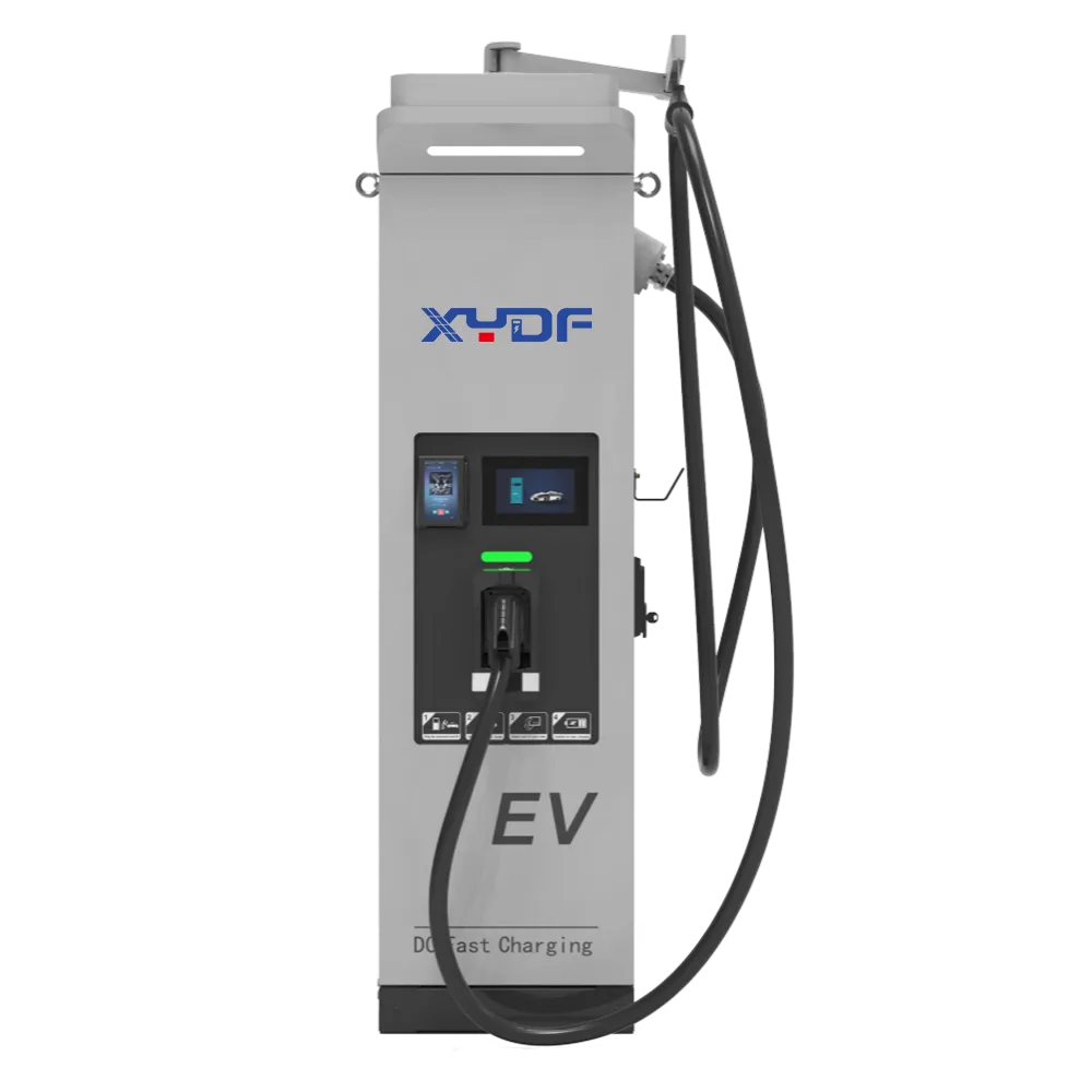
When an apartment-property manager in Austin encountered breakers tripping as residents began charging after work, she first proposed buying fewer chargers. The visible failure came within minutes of the evening peak: circuits opened and residents lost access. The reversal was that charger count was not the root cause. Circuit design, continuous-load treatment, each vehicle’s onboard charger and the operating controls for simultaneous sessions had never been designed together.
Summary: A level 2 ev charger normally supplies 208/240 V AC in North American contexts, but actual charging speed is limited by the vehicle’s onboard charger, circuit, temperature and battery state. Select the circuit and equipment together, confirm local permit and installer requirements, and test simultaneous use at workplaces and apartments. In the United States, continuous-load calculations are governed by locally adopted NEC requirements; a licensed local professional should confirm the applicable edition and design.
A Level 2 system is a managed electrical and parking asset, not merely a connector. The U.S. Department of Energy’s Alternative Fuels Data Center distinguishes Level 1, Level 2 and DC fast charging; use the distinction to match dwell time and electrical capacity rather than to promise a fixed number of miles per hour.
Power, voltage and the vehicle limit
North American Level 2 equipment typically operates at 208 V or 240 V AC, but service characteristics and local rules vary. The EVSE communicates available current; the vehicle converts AC to DC through its own onboard charger. Therefore a higher-rated wall unit cannot make a vehicle draw beyond its AC limit. The onboard charger limit, circuit rating, voltage, battery temperature and state of charge determine the session outcome.
Connector context is market-specific. SAE J1772 has been common for North American AC charging, while other markets commonly use different interfaces; NACS/J3400 equipment and approved adapters may also be relevant in North America. Confirm the vehicle’s inlet, the intended market and manufacturer-approved adapter path. Do not treat a connector reference as an installation approval or a universal compatibility claim.
Compare Level 1, Level 2 and DC charging
A level 2 ev charger fits long dwell—overnight home parking, workplaces and apartment garages—when the circuit and vehicle support it. DC charging converts power in the station and can suit shorter dwell, but it has different utility, civil and demand-management implications. See the guide to EV charger levels and Level 2 versus Level 3 EV charger comparison for supporting context.
For example, a 50 kW DC unit may suit a vehicle parked for an hour or more, but it cannot guarantee a 50 kW session at every battery temperature or state of charge. This is illustrative, not a delivery promise. Compare voltage range, current, and power-sharing logic with vehicle data sheets; validate with a controlled session and logged meter data. For higher-power sites, review how a 350 kW DC fast charger delivers power safely.
| Dimension | Level 1 AC | Level 2 AC | DC charging |
|---|---|---|---|
| Typical use | Very long dwell | Home, workplace, apartment | Shorter dwell and high utilization |
| Power conversion | Vehicle onboard charger | Vehicle onboard charger | Station power electronics |
| Speed constraint | Outlet and vehicle limit | Circuit and vehicle limit | Vehicle battery acceptance and station capacity |
| Site focus | Existing outlet condition | Dedicated circuit and simultaneous load | Utility capacity, civil works and demand profile |
Check Tesla/NACS, CCS, adapters, and the user journey
Adapters can broaden access, but they should be governed, not assumed. Verify the vehicle maker’s approved adapter path, charger interface, electrical limits, cable reach, and responsibility for damaged adapters. An adapter cannot solve incompatible authorization or unavailable power. For mixed fleets, native connector coverage is easier to operate than untracked adapters at every shift change.
Compatibility continues after the plug connects. Confirm the required app, RFID, QR flow, roaming, payment terminal, and backend protocol. OCPP is a communications protocol, not a universal interoperability guarantee; specify the version, API functions, tariff controls, and reports, then test them with the selected network. ISO 15118 features likewise require confirmation from both vehicle and charging-system parties.
Confirm building electrical capacity and installation fit
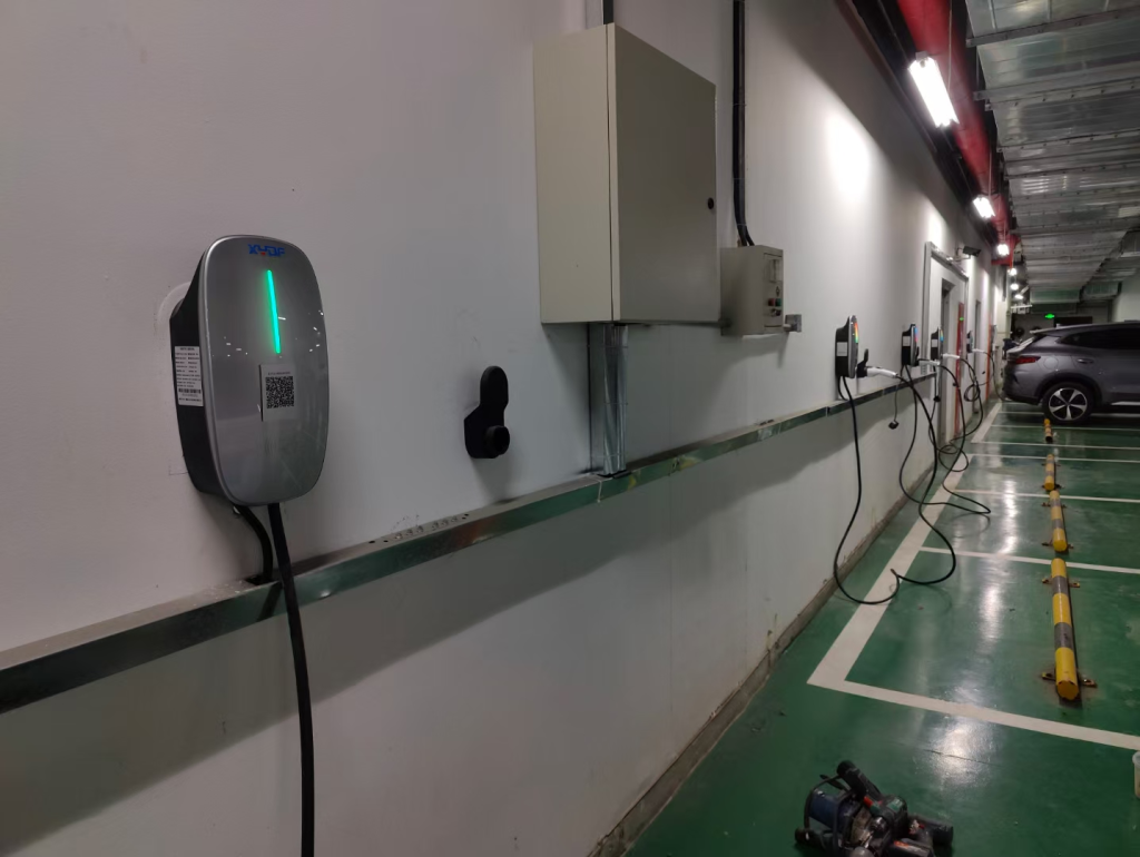
Home, apartment, depot, and public sites each have different upstream constraints. A charger may fit the vehicle yet exceed spare panel capacity, require a service upgrade, or conflict with conduit routes. In Toronto, a licensed electrical contractor should assess service, panel, feeder, protection, grounding, load calculation, and local authority requirements. Load management must be documented and tested under simultaneous demand.
| Application | Key compatibility question | Useful acceptance check |
|---|---|---|
| Home | Can the service and panel support the planned circuit? | Licensed load calculation and permitted installation |
| Apartment | Can multiple users authenticate and share constrained capacity? | Concurrent-session and RFID/account test |
| Fleet depot | Do vehicle routes match overnight AC or DC turnaround? | Vehicle matrix plus full-shift load profile |
| Public site | Do payment and connector choices serve target drivers? | End-to-end payment and charging trial |
Sizing decision table
| Equipment output | Circuit/continuous-load context | Typical use case | Verification |
|---|---|---|---|
| 16 A | Confirm dedicated circuit and local continuous-load treatment | Long-dwell home or small workplace | Panel, conductor and vehicle-limit review |
| 32 A | Confirm circuit rating and calculated building load | Home and routine workplace dwell | Permit/installer and simultaneous-load check |
| 40 A | Confirm branch circuit and protective-device design | Higher-use residential or workplace | Nameplate, wiring and vehicle OBC check |
| 48 A | Often requires careful feeder/panel assessment | High-utilization AC parking | Local adopted code and load calculation |
| 80 A | Service and distribution capacity are central | Commercial managed charging | Engineer/installer design and control testing |
In U.S. NEC contexts, EV charging is generally treated as a continuous load for calculation purposes, but code adoption, amendments and the appropriate design method must be confirmed locally. A continuous-load calculation is not a quick nameplate comparison: it considers existing demand, feeder and service capacity, conductor and overcurrent protection, and how the selected equipment is controlled. Electrical work, permits and inspection requirements are local matters; this guide is not electrical or legal advice.
For a residence, begin with actual panel capacity and the vehicle’s normal arrival/departure window. For an apartment or workplace, add the number of active ports, tenancy loads, access rules and a policy for coincident demand. A 48 A EVSE is not automatically a better outcome than several managed 16 A or 32 A ports; the useful design is the one that meets dwell requirements without exceeding the verified site envelope. Read how many amps an EV charger needs before choosing an output rating.
Standards, compliance, and a practical buying sequence
Multi-unit and workplace operations: policy, controls and maintenance handover
At a multi-unit residence or workplace, the physical charger is only one part of the service. The operator must decide who can use a port, when it can be used, how drivers are identified, how costs are allocated, how a vehicle is moved after charging, and who responds when a session fails. These decisions should be made before launch because they influence the number of shared ports, network settings, signage, support training and the resident or employee experience. A technically successful installation can still underperform when access rules are unclear or the same few users occupy the most convenient spaces.
Start with a written user policy. It can define eligible users, assigned versus shared bays, charging hours, idle or parking rules, approved connectors and adapters, visitor access, fault reporting and escalation. A property manager should also determine whether energy is included in rent, billed by session, reimbursed by an employer or allocated through another approved method. Billing and metrology obligations vary by location, so obtain local advice before representing displayed energy data as a billable measurement. Explain the policy in short driver-facing instructions, not only in a technical manual.
Authentication should serve the operating model. RFID cards, mobile apps, QR-based starts or vehicle-linked accounts each have different administration and support implications. For a small owner-occupied workplace, a simple managed list may be sufficient; for an apartment property with turnover, the system needs a reliable process to add, suspend and remove users. Identify who owns the account, who can export data, how credentials are recovered after a phone loss, and what happens if the network service changes. A basic privacy review is prudent because charging records can reveal work hours, location patterns and user identities.
Load management converts a verified site limit into an operating rule. It may allocate capacity equally, prioritize scheduled users, preserve a minimum building reserve, or delay lower-priority sessions until demand falls. The policy must match the algorithm. If all users expect immediate maximum output, a fair-share system may seem like a fault even when it is protecting the electrical service. Display or communicate the reason for reduced output, and give a property or facilities owner a controlled method for responding to urgent exceptions. Do not grant unrestricted manual overrides that can defeat the electrical design.
Illustrative example: a workplace has eight active ports but has elected a verified aggregate charging limit during the building’s afternoon demand period. At 16:30, four drivers connect at once. A configured controller can divide the available capacity and increase it later when building demand falls, provided that the selected equipment, site design and local requirements support that control. The useful operational metric is whether drivers receive the agreed energy by their stated departure time, not whether each port always displays its maximum rating. Actual limits and calculations must be designed for the specific site.
Commissioning should include the operational policy, not just electrical tests. Create test users with different access rights, then check account creation, start and stop behavior, reporting, access removal, simultaneous sessions, loss of communications and restoration of data after a network interruption. Confirm that load-management setpoints are protected against accidental changes and that authorised staff know how to identify a deliberate curtailment versus a fault. Run at least one realistic user journey: arrival, parking, authorization, connection, charging, notification, unplugging and dispute or support request.
Maintenance handover needs named responsibilities. The property owner may own the asset, a facilities team may inspect the parking area, an electrical contractor may handle electrical work, and a network provider may resolve software alarms. Put these roles in a contact matrix that says who receives each alarm, expected response path, safe isolation authority and record location. Keep equipment manuals, as-built drawings, warranty terms, serial numbers, configuration exports and commissioning records together. Before any maintenance work, follow the manufacturer’s instructions and the applicable local safety procedures.
A preventive programme should include visual checks for damaged cables, connector condition, mounting damage, water ingress, signage, bay obstructions and access to emergency information. Remote monitoring can help identify repeated failed starts, communication loss, fault codes or unusual energy patterns, but it does not replace site inspection. Track causes separately: a disconnected cable, unavailable network, vehicle rejection, building protection event and equipment fault call for different corrective actions. Repeated events should be reviewed against the original drawings, user policy and controller settings instead of being closed as generic “charger issues.”
Finally, set a change-control process. Adding a port, changing output settings, replacing a communications module, updating firmware, changing a tariff or revising the user policy can change the operation of the whole site. Record the requested change, technical owner, impact on the verified capacity, test required and rollback path. At a multi-unit property, inform users of material changes early; at a workplace, align facilities, HR, finance and IT. This disciplined handover turns a Level 2 deployment from an isolated amenity into a maintainable service that can grow without losing control of electrical capacity or user trust.
Site survey, electrical-service planning and commissioning handover
Before selecting equipment, make the site survey a controlled record rather than a walk-through. Identify the service voltage, service rating, main and distribution panels, available breaker spaces, feeder routes, transformer or utility constraints, existing building demand, parking ownership, conduit paths, trenching constraints, drainage, lighting, communications coverage and accessible routes. Photograph labels and available drawings, but have a qualified local electrical professional validate ratings and field conditions. A charger location that is convenient for parking can still be expensive or unsuitable if it crosses fire separations, blocks an accessible path, needs long cable runs, or cannot be isolated safely for maintenance.
Electrical-service planning starts with measured demand where it is available. Collect interval utility data long enough to show ordinary peaks, seasonal equipment and occupancy patterns; an office can have a very different evening load from an apartment property. Then identify the proposed charging operating window and how many ports may request power simultaneously. Existing load, planned building changes and future ports all matter. A site survey should also record fault-current information, earthing arrangements, panel condition, protective-device coordination, available space for metering and the utility’s process for an upgrade. These items are design inputs, not assumptions that a charger vendor can safely infer from a parking count.
In U.S. NEC contexts, continuous-load treatment is a key design question, but local adoption and amendments must be confirmed with the authority having jurisdiction and qualified installer. The calculation is not simply “charger amps multiplied by ports.” It needs the applicable rules, equipment ratings, conductor and overcurrent-protection selection, demand assumptions, feeder/service capacity and the behaviour of any approved control system. The building owner should keep the calculation, drawings and approval path in the project record. This article does not provide electrical or legal advice.
Illustrative example: a workplace considers ten ports capable of 32 A each. Treating every port as simultaneously active produces a very different planning result from a verified controller that limits aggregate charging load to a defined site value. That controller can be useful only when its control architecture, failure mode, measurement point, settings access and commissioning tests are documented. If communications fail, the system must respond as designed; an undocumented assumption that “software will manage it” is not a capacity study. The exact numerical design must be performed for the actual service and locally applicable requirements.
Illustrative example: an apartment garage has 208 V service, residents commonly arrive between 17:00 and 20:00, and vehicles remain until morning. The useful question is not whether every bay can receive maximum output at 18:00. It is whether the verified energy can be allocated across the dwell window while preserving tenant loads and an agreed reserve. A schedule, access policy and a managed-load limit may support more residents than an unmanaged design, but the result depends on vehicle acceptance, arrival distribution, building load and local rules. Review real session data after launch rather than treating the pilot schedule as permanent.
Survey the physical operation as carefully as the one-line diagram. Mark vehicle approach, door swing, cable reach, bollards, wheel stops, snow or water exposure, delivery access and technician working space. Confirm who controls each parking space and who may authorize civil work. In multi-unit properties, define allocation rules before construction: assigned bays, shared bays, visitor use, billing, move-out handling and response to a blocked connector. In workplaces, define whether charging is an employee benefit, reimbursable expense or managed amenity; these choices shape authentication, energy reporting and support escalation.
Commissioning should prove the installed system, not merely power it on. Create a handover checklist with asset serial number, location, circuit reference, equipment rating, firmware version, communications identifier, drawings, permits, test records, user instructions, emergency procedure and support contacts. Witness functional checks for connector latch, session start and stop, emergency stop, protection functions as applicable, meter-data visibility, authentication, simultaneous sessions, managed-load response and recovery from a communications interruption. Record the test method and outcome, including any limitation discovered during the test.
For shared sites, run a realistic operating test during the expected busy window. Confirm that drivers can find the correct bay, read status indicators, start a session and report a fault without accessing electrical equipment. Test what the property manager sees when the aggregate limit is reached and when a port is unavailable. Handover should name an owner for settings changes, access credentials, tariff or reimbursement rules, firmware review and incident escalation. This operational evidence is as valuable as the electrical drawings because it exposes queueing, unclear ownership and unexpected concurrent demand before they become resident or employee complaints.
Finally, establish a review loop. During the first month, compare meter data, active-port count, load-management events, interrupted sessions and user feedback with the original assumptions. Investigate repeated derating or trips with the installer and equipment supplier; do not solve a protection issue by increasing settings without a documented engineering review. Retain the baseline configuration so that future ports, vehicle changes or software updates can be assessed against the original site envelope. A well-kept handover pack turns a one-time installation into an operable charging service.
Selection decision tree
- Is the vehicle normally parked long enough to recover required energy with AC? If no, assess a different charging strategy.
- Does the vehicle’s AC onboard charger accept the proposed output? If no, select for the vehicle limit rather than the EVSE nameplate.
- Does the site have verified spare capacity after applicable continuous-load calculations? If no, study managed charging or electrical upgrades.
- Is the location homeowner, landlord, employer or public operator controlled? If shared, define authentication and cost allocation before installation.
- Can the local installer, permit authority and utility requirements be satisfied? If uncertain, pause procurement until the route is confirmed.
This decision tree avoids a common purchasing error: choosing a charger based on maximum advertised output before the vehicle, building and user workflow have been checked. A level 2 ev charger is a practical choice only when its output can be used safely and consistently within that complete system. For household operating routines, see how to charge an EV at home; decisions about self-installation should start with whether you can install an EV charger yourself and then local licensed-professional requirements.
Standards define scope; they do not automatically certify a product or prove project compliance. SAE J1772 and SAE J3400 address charging interfaces; IEC 61851 addresses conductive charging systems, and IEC 62196 covers plugs and inlets. The National Electrical Code and Canadian Electrical Code govern installation in their jurisdictions. State the destination market, intended use, required approvals, and test evidence; unsupported claims or a mismatched installation can delay commissioning.
- Create a fleet matrix: vehicle model, inlet, approved adapter, onboard AC limit, DC voltage range, and route dwell time.
- Specify connector allocation and a controlled adapter policy, including ownership and inspection.
- Write the backend requirement: user authentication, payment, OCPP/API scope, data ownership, and support escalation.
- Obtain an electrical design and load calculation, then test simultaneous sessions before operational handover.
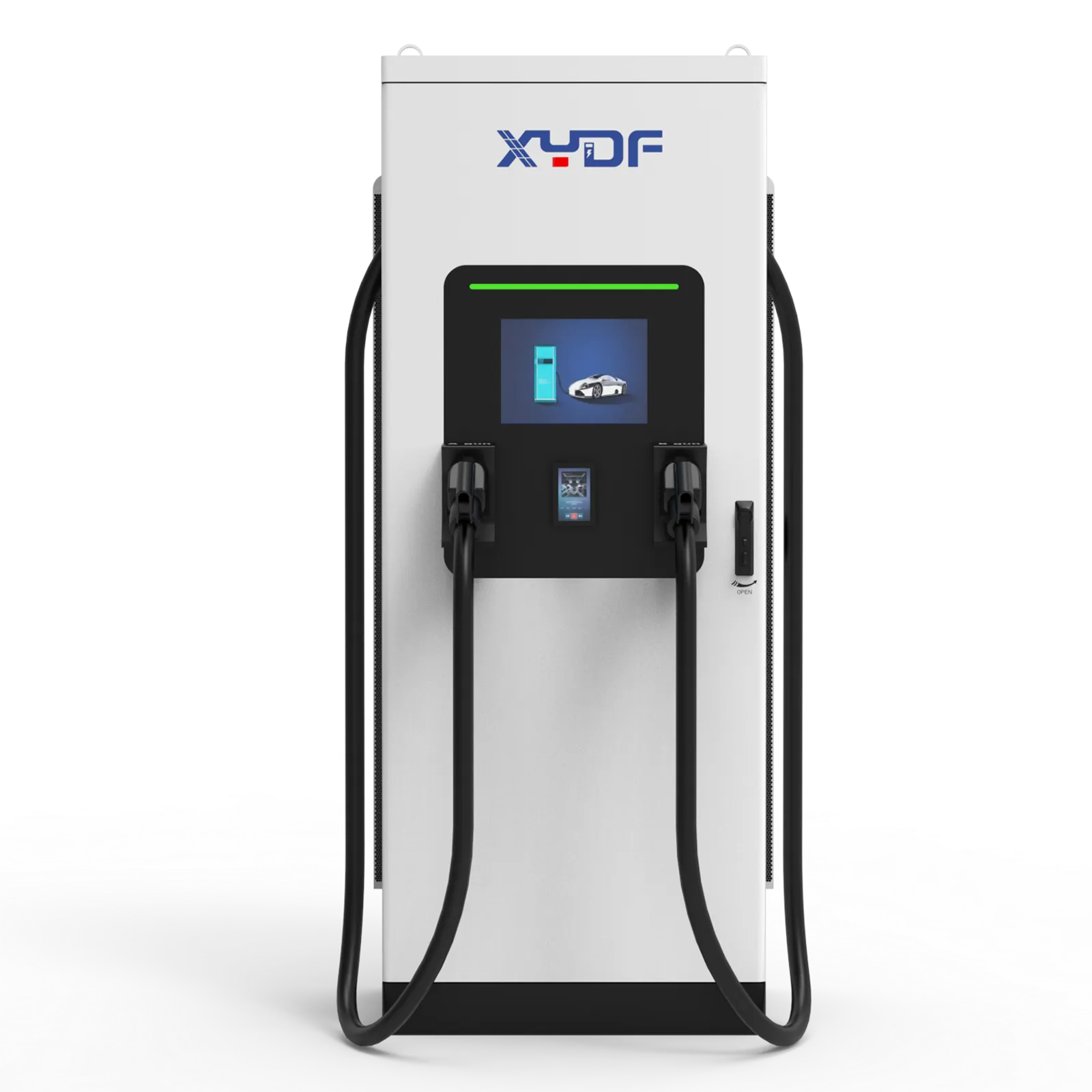
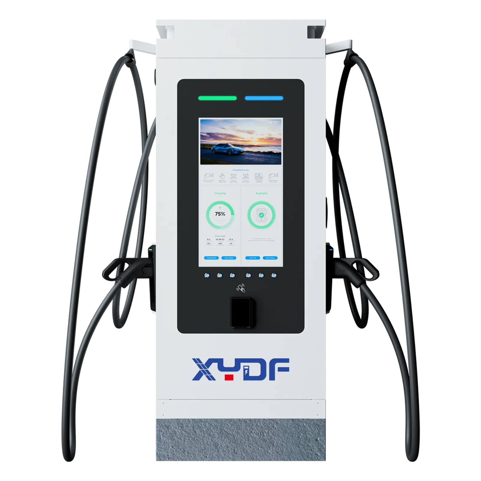
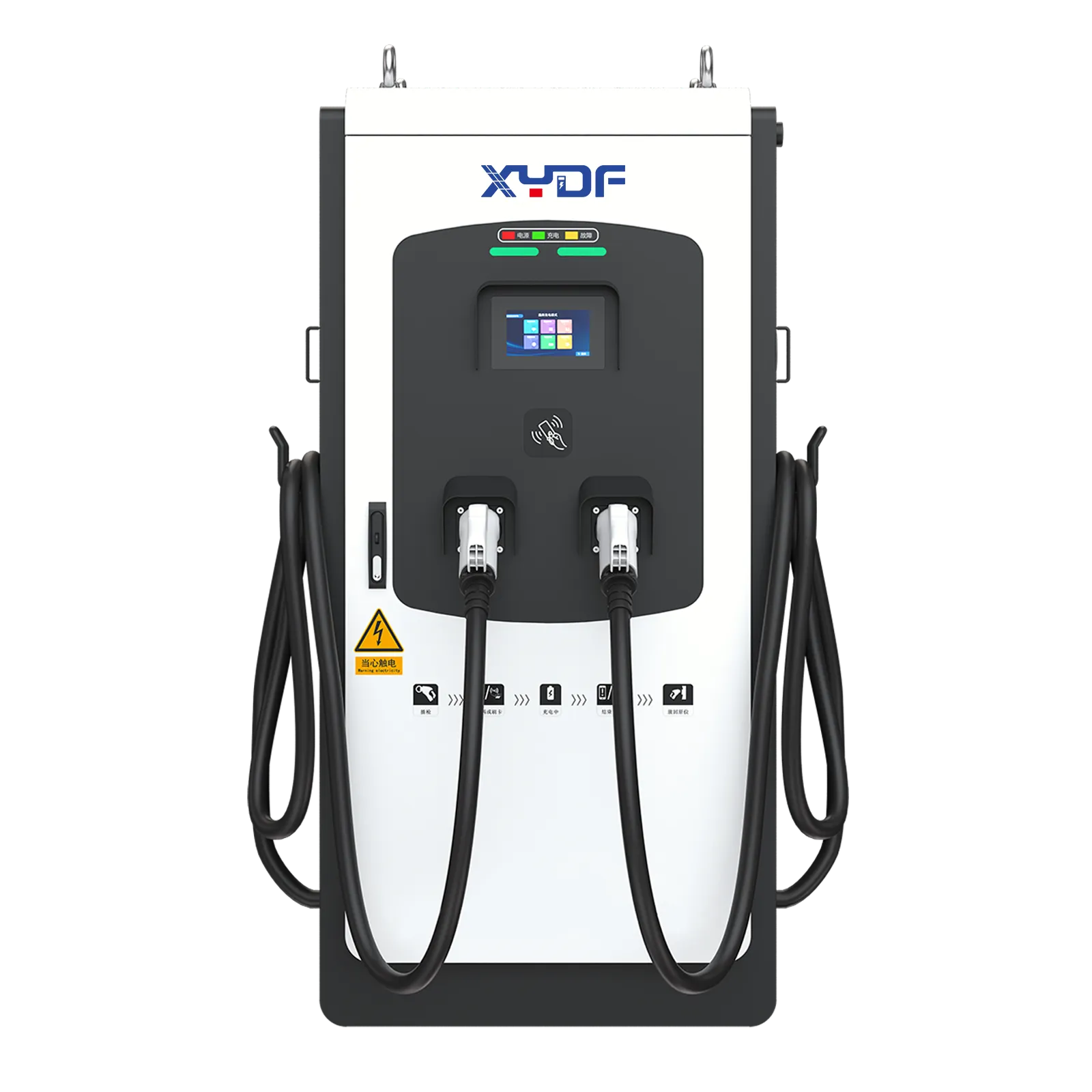
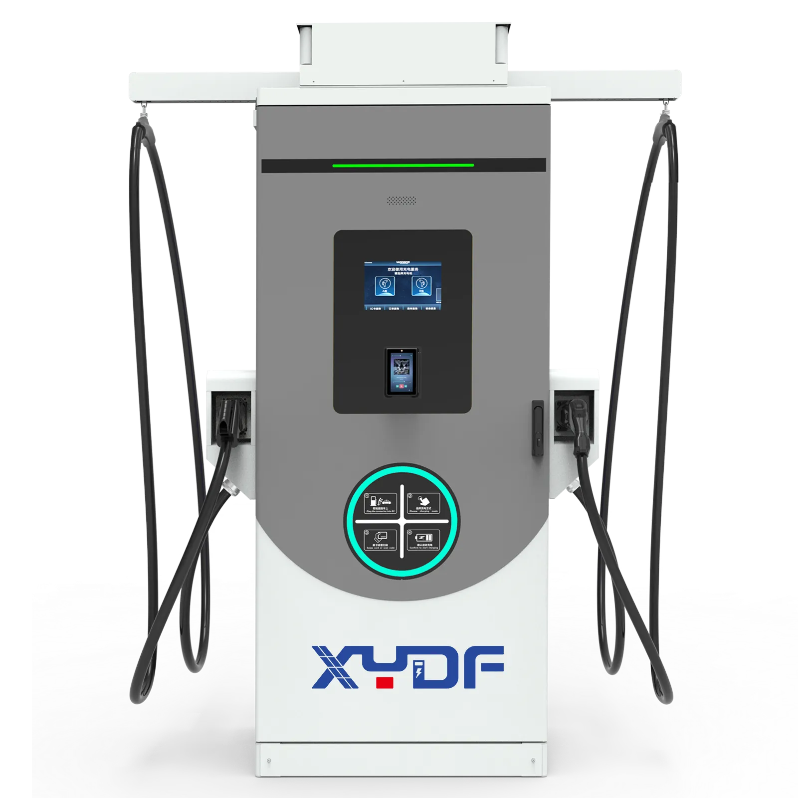
XYDF can support buyers comparing configurable EV charging equipment across AC chargers, DC fast chargers, and charging-station applications. For long-dwell deployments, evaluate AC EV chargers with load management and vehicle limits. Where grid capacity is constrained, review battery-storage sizing for an EV charging station.
Frequently asked questions
How do I know if a charging station is compatible with my car?
Check the vehicle’s inlet type, its maximum AC onboard-charger rating, and its supported DC charging interface and voltage range. Then confirm the charger connector and any approved adapter with the vehicle manufacturer, and test a session before a fleet-wide rollout.
What voltage does a Level 2 EV charger use?
In North American applications, Level 2 equipment typically uses 208 V or 240 V AC. Actual service voltage, equipment ratings and permitted installation details depend on the site and local rules, so an installer should verify the project rather than relying on a generic description.
Will a 48 A charger charge every EV at 48 A?
No. The EVSE advertises available current, while the vehicle’s onboard charger controls what it accepts. Battery state, temperature and voltage also affect actual charging; review the vehicle manual and test the intended configuration.
Is a plug-in or hardwired installation better?
A hardwired installation can be appropriate where the equipment and local rules require or support it, while a receptacle-based arrangement adds its own rating and condition checks. The correct choice depends on the listed equipment instructions, site design and local installation requirements.
Can an apartment add many Level 2 ports at once?
Possibly, but the building must evaluate feeder and service capacity, tenant loads, operating schedules and local permit requirements. Load management can allocate a verified site limit across active ports, but it needs clear settings, commissioning and a fallback process.
How should a workplace select chargers?
Start with employee dwell, vehicle limits, parking turnover and the verified electrical envelope. Set access, reimbursement and support rules, then commission concurrent sessions before opening the system.
References & Related Reading
- U.S. Department of Energy Alternative Fuels Data Center — Electric Vehicle Charging Stations
- SAE International — J1772 Electric Vehicle Conductive Charge Coupler
- SAE International — J3400 North American Charging System
- NFPA 70: National Electrical Code information
- U.S. Department of Energy: charging electric vehicles at home
Charging selection is proven at the vehicle, circuit and user level. Late in a sourcing process, XYDF/Xinya EE can be considered alongside other suppliers for AC equipment whose configuration, documentation and local installation route have been defined. Contact the team to review AC EV charger options against the verified project requirements.