 شركة شينيا دونغفانغ لتكنولوجيا الكهرباء المحدودة.


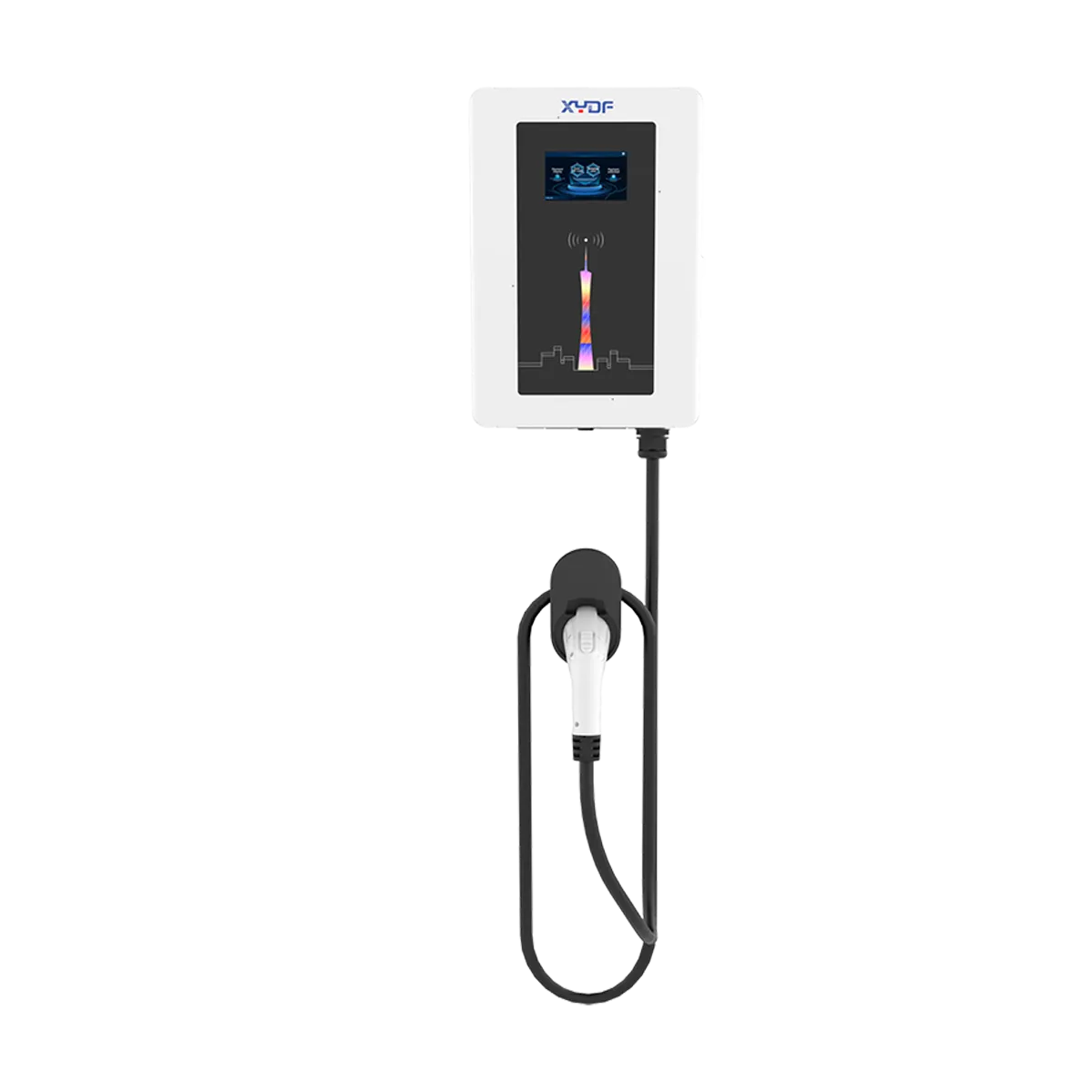
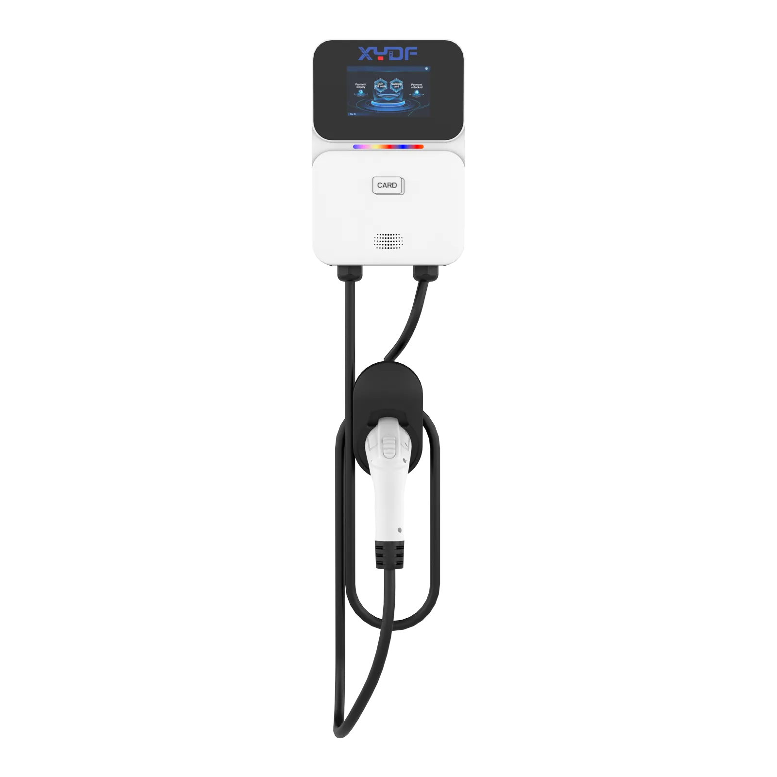
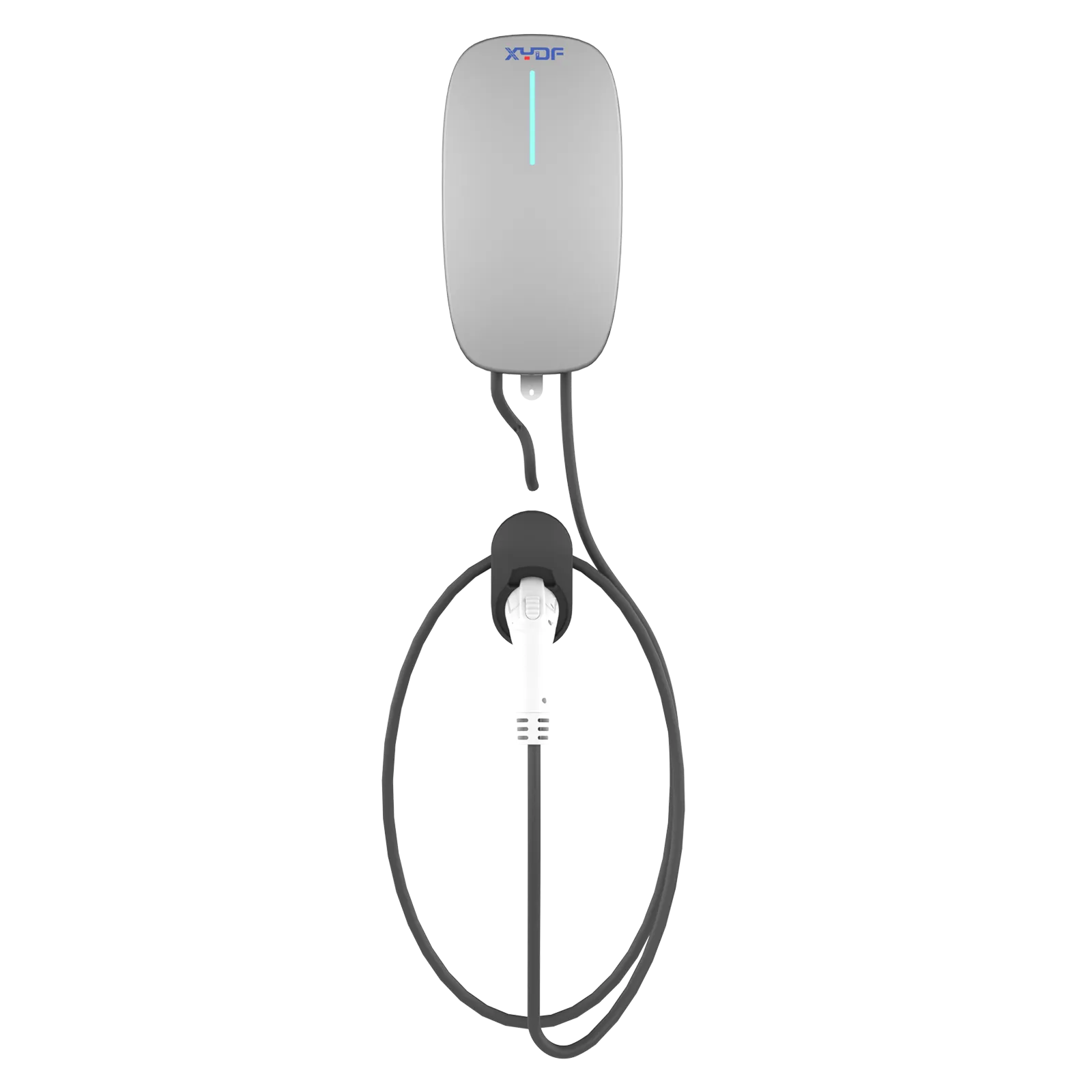
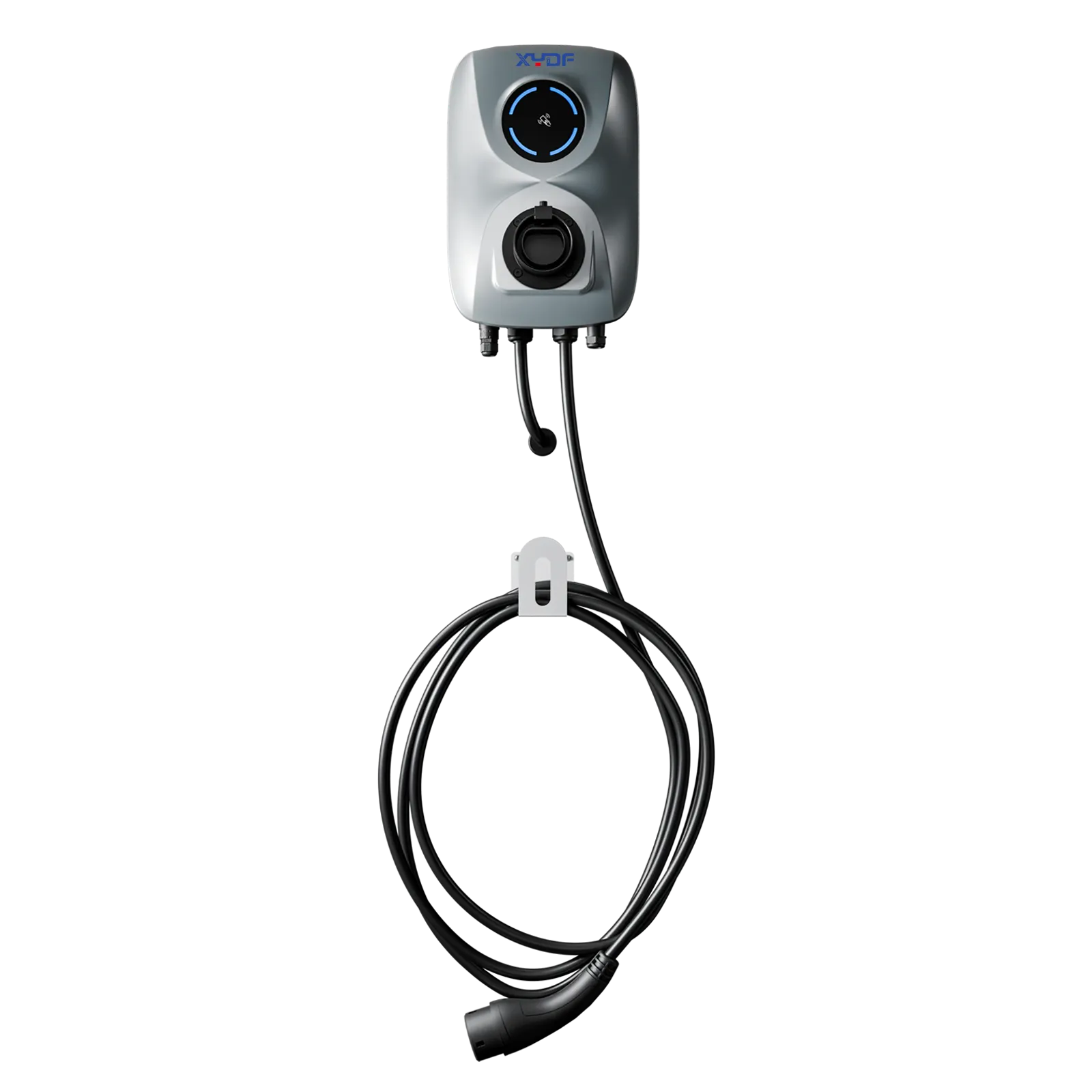
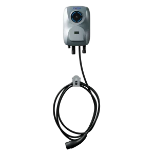
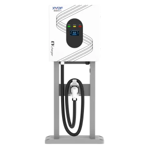

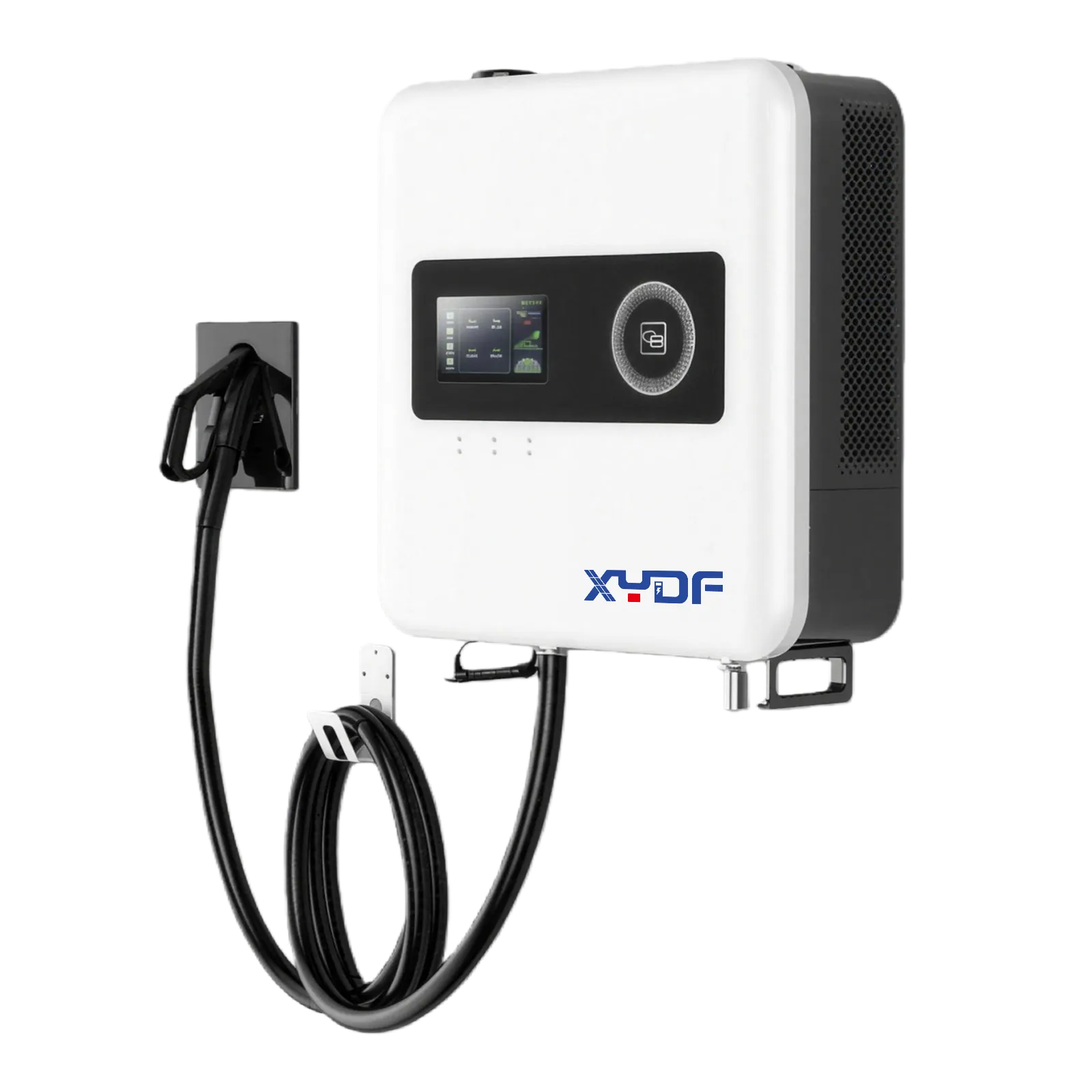
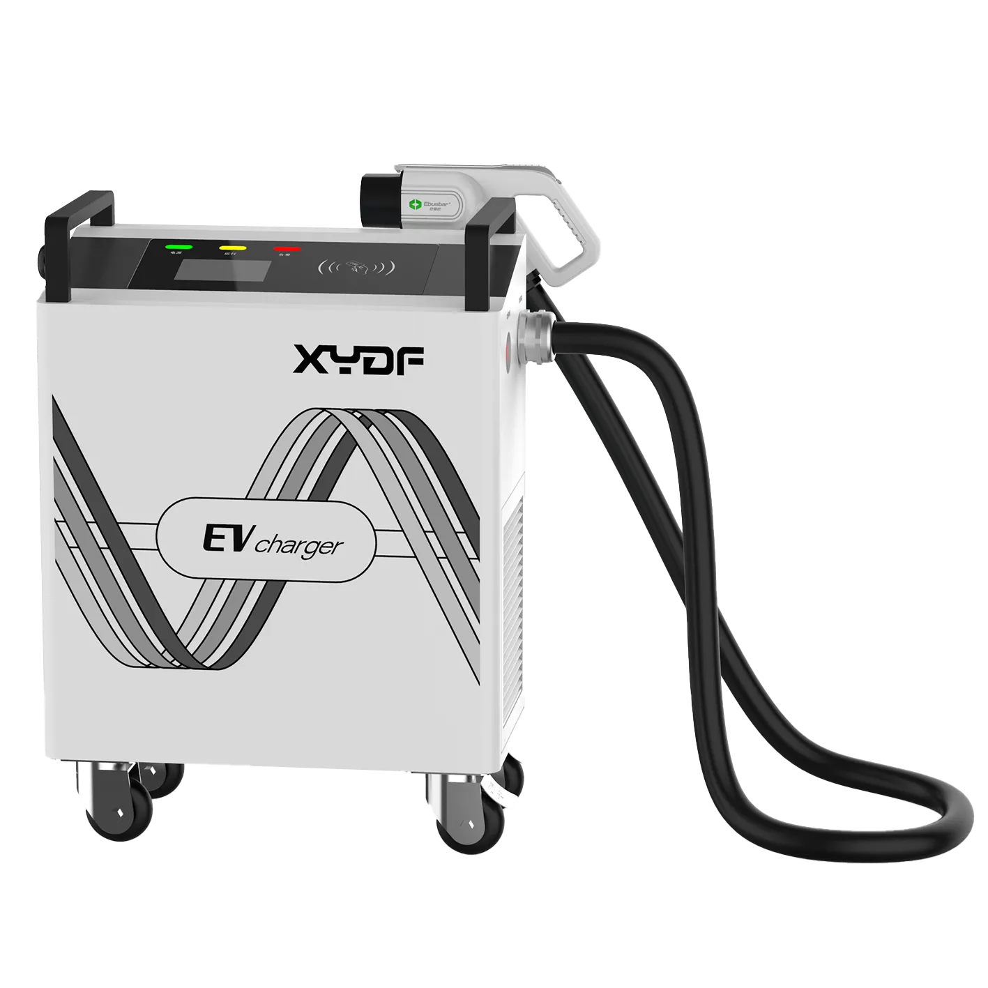
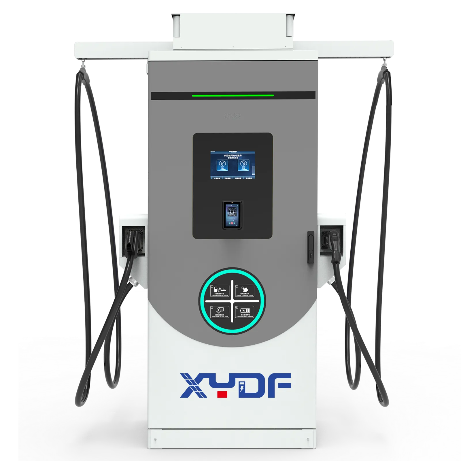
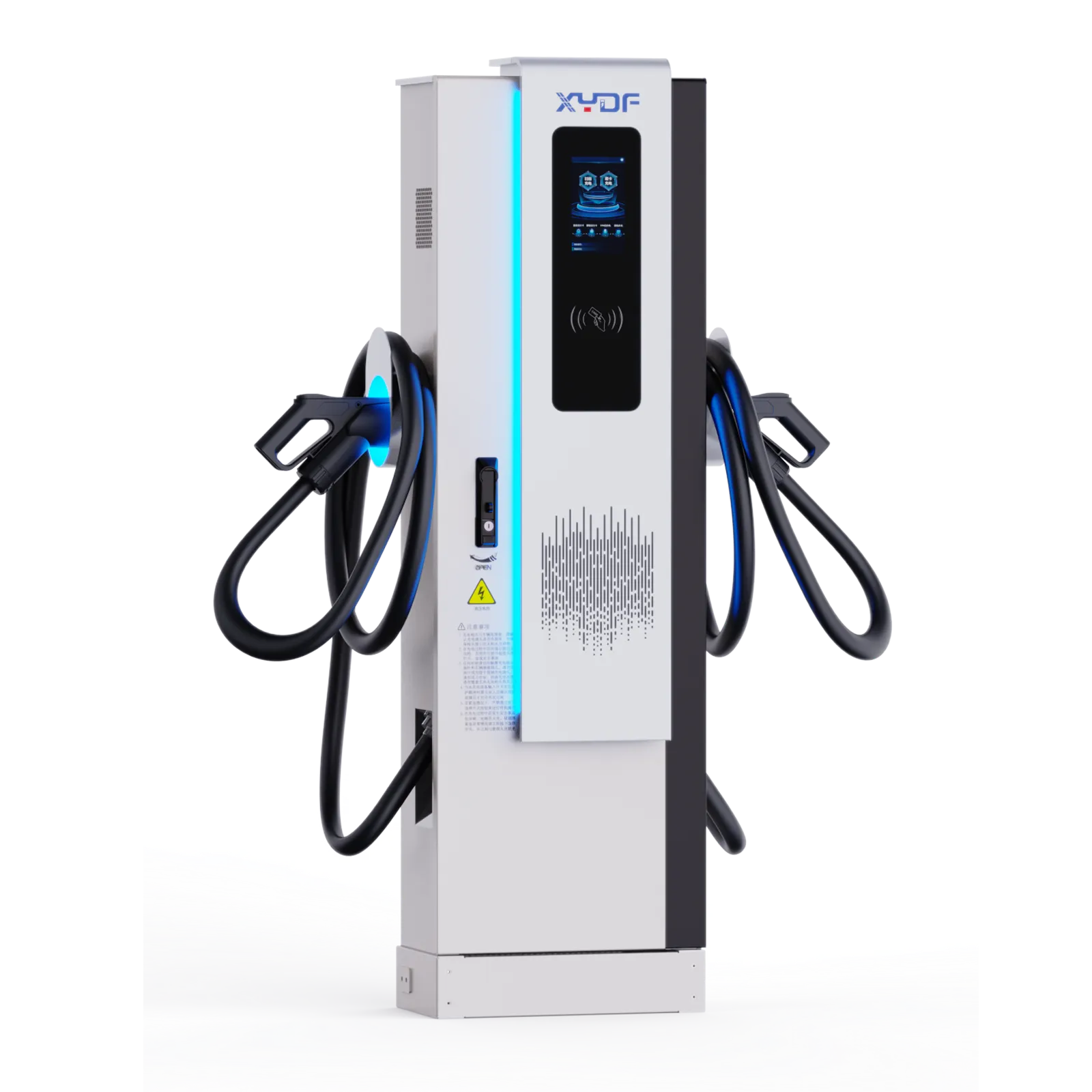
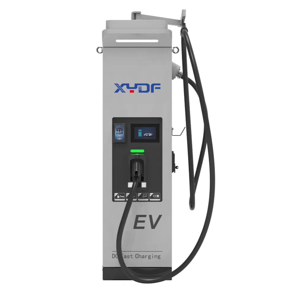
An EV charger specification that says only “DC leakage protection included” leaves an important question unanswered: which device detects the fault, and which device disconnects the supply? That gap can delay approval, complicate commissioning, or leave the installer buying protection that the original quotation did not include.
When a procurement brief uses the phrase DC leakage protection EV charging, treat it as a requirement to document the detector, switching path, test method and applicable installation rule, rather than as proof that one built-in feature covers the entire circuit.
ملخص: For an AC charging installation, a documented Type A RCD plus appropriate 6 mA DC residual-current detection can be an accepted alternative to a Type B RCD where the applicable installation rules permit it. A DC detector alone does not provide the complete protection arrangement. Check the charger documentation, the adopted electrical code, and the disconnection function before specifying either option.
The practical RCD type B vs RCD-DD decision is therefore about a system, not two interchangeable components. IEC 60364-7-722 addresses EV supply installations, while IEC 62955 addresses residual direct-current detecting devices for Mode 3 charging. Their scopes explain why the charger, circuit protection, and installation must be evaluated together.
What RCD-DD and Type B RCD Actually Do
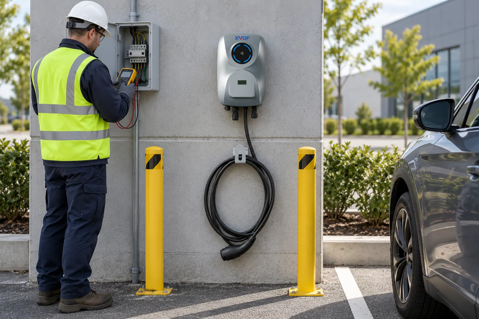
RCD-DD is common search and supplier terminology. IEC 62955 uses RDC-DD: residual direct-current detecting device. When reviewing an RCD-DD EV charger specification, establish whether the claim refers to a sensor, an integrated detecting and switching assembly, or a detector that operates a separate switching device. These are materially different procurement descriptions.
Why DC detection matters on an AC charging circuit
An AC charger supplies the vehicle’s onboard charger, which contains power electronics. Certain faults can introduce smooth DC residual current into the AC supply circuit. That current can affect the operation of a Type A RCD; the issue is not solved simply by choosing a higher-current circuit breaker.
Type A devices detect specified AC and pulsating DC residual currents, but they are not general-purpose smooth-DC protective devices. In the Type A plus RDC-DD arrangement, DC detection limits this particular exposure while the Type A RCD provides its specified residual-current protection. The commonly specified 6 mA DC function belongs to this arrangement; it is not the same thing as a 30 mA AC additional-protection rating.
Schneider Electric’s installation guide, updated 5 August 2026, describes individual AC connection protection with an RCD rated no higher than 30 mA: Type B, or Type A/F combined with IEC 62955 RDC-DD protection. This manufacturer guidance explains an IEC-based arrangement, not universal installation acceptance; the upstream RCD and complete detection-to-opening path still need coordination.
What a Type B RCD adds
A Type B RCD responds to smooth DC as well as other residual-current waveforms within its specified operating range. IEC 62423 sets additional requirements for Type F and Type B RCDs, alongside the relevant base product standards. Frequency response, rated current, supply conditions, and installation compatibility still need checking; “Type B” is not a complete specification.
A Type B RCD EV charger installation may use a separate protective device in the distribution board rather than one inside the charger. Its location affects the part of the circuit protected. Neither an RCD nor a DC detector replaces required overload and short-circuit protection; an RCBO combines functions only within its declared ratings and approvals.
| Selection point | Type A RCD plus RDC-DD | قاطع تيار تسرب أرضي من النوع B |
|---|---|---|
| Core function | Type A protection combined with a dedicated smooth-DC detection and disconnection function | Residual-current protection including smooth DC within the device’s declared scope |
| Standards evidence | Applicable RCD product standard, IEC 62955 evidence, and documented integration | Applicable base RCD product standard plus IEC 62423 evidence |
| Switching responsibility | Must identify how the detector causes the required supply disconnection | Performed by the RCD’s switching mechanism within its specified application |
| Installation acceptance | Conditional on adopted rules and charger instructions | Conditional on ratings, coordination, adopted rules, and charger instructions |
| Cost drivers | Detector integration, contactor arrangement, external RCD, and verification work | Device selection, board space, upstream coordination, and suitable test equipment |
| Main documentation risk | A sensor described as if it were a complete protective assembly | A Type B label used without waveform, rating, and installation details |
EVSE Protection Wiring: Where the Devices Belong
A wiring review should trace the charging circuit from the distribution board to the vehicle connection. Identify the overcurrent device, the RCD, the residual-current sensor, the switching contacts, and the protective conductor. For EVSE residual current protection, a component list is not enough: the diagram must show what happens after a fault is detected.
The manufacturer’s circuit design determines which live conductors pass through the residual-current sensing arrangement. Protective earth must not be treated as a normal current-carrying conductor through that measurement path. Shared or incorrectly routed neutrals can create misleading residual-current readings and unwanted operation. Follow the device instructions rather than reproducing a generic internet wiring diagram.
With a detector-operated contactor, review the specified disconnection path, power-supply dependence, self-monitoring, and fault response. Ask what happens if the detector loses supply or its output circuit fails. Do not assume that a low-voltage alarm output or a software notification necessarily provides the required protective disconnection.
For multiple charging points, check the protection arrangement for each final circuit and each connection point under the adopted installation rules. Several chargers on a shared upstream RCD also require a coordination review: cumulative leakage and a common trip can interrupt more than the faulty outlet. A downstream DC detector does not automatically make every upstream device suitable.
Nuisance tripping is a diagnostic problem, not a reason to weaken protection
First distinguish a genuine insulation fault from standing leakage, incorrect neutral routing, damaged cables, moisture, or poor coordination. A leakage-current clamp and a suitable installation tester answer different questions: one helps investigate operating leakage, while the other applies controlled tests to the protection arrangement.
Record whether tripping occurs during standby, connection, charging startup, or sustained charging. Investigate one circuit at a time using an approved isolation procedure. Changing from Type A to Type B may address a waveform-selection issue, but it will not repair a damaged cable, incorrect wiring, or water ingress. Raising a protection threshold without an approved design basis is not a commissioning remedy.
Which Arrangement Fits AC Charging and DC Fast Charging?
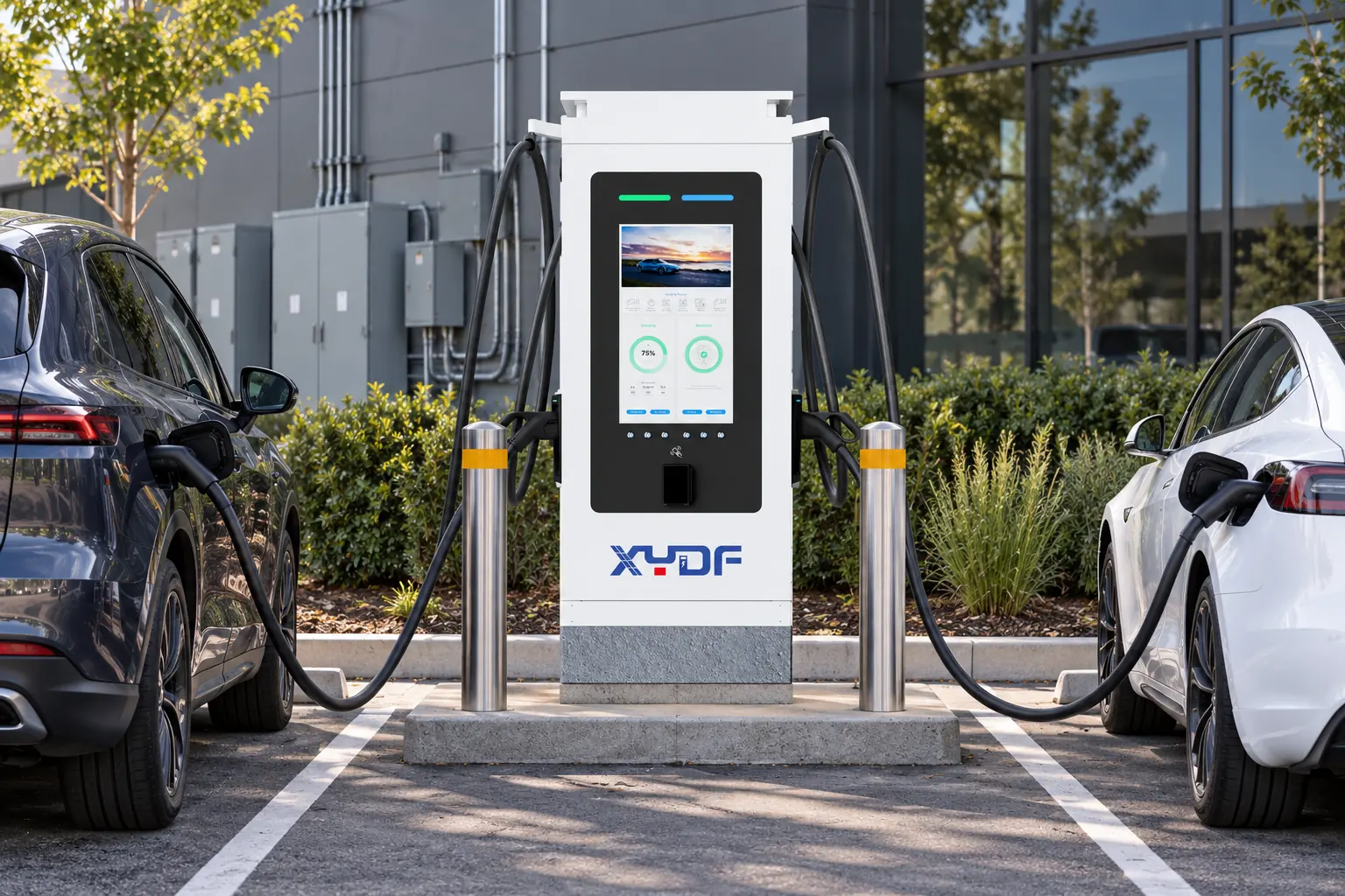
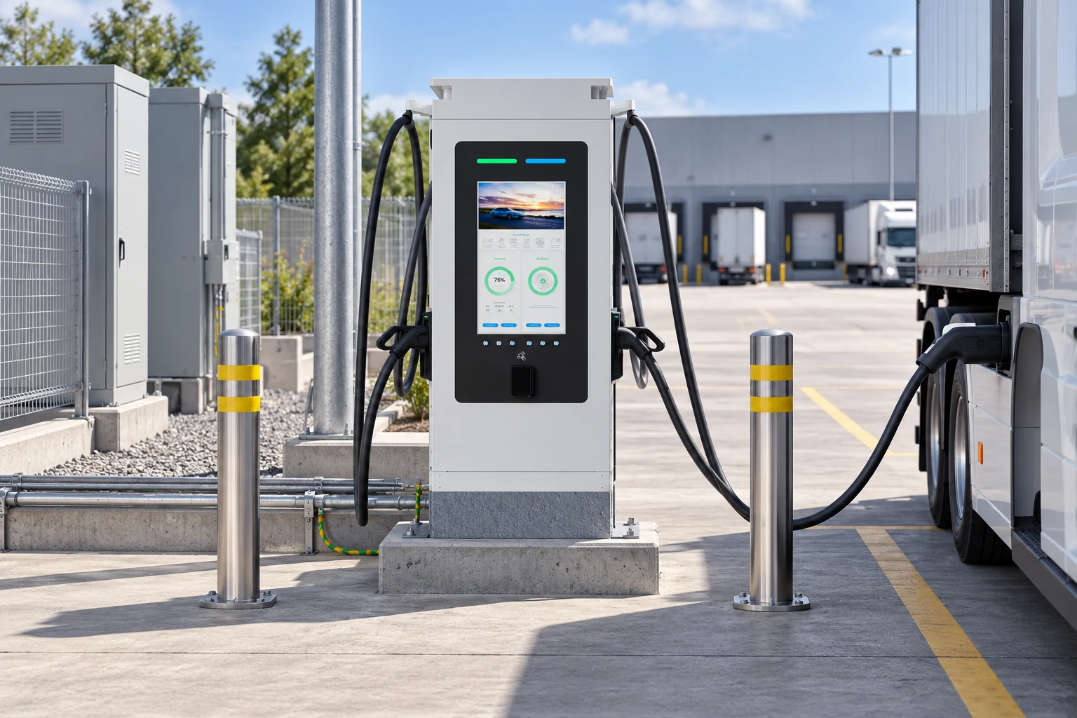
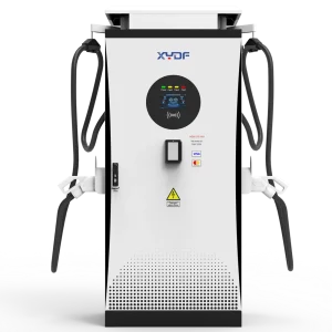
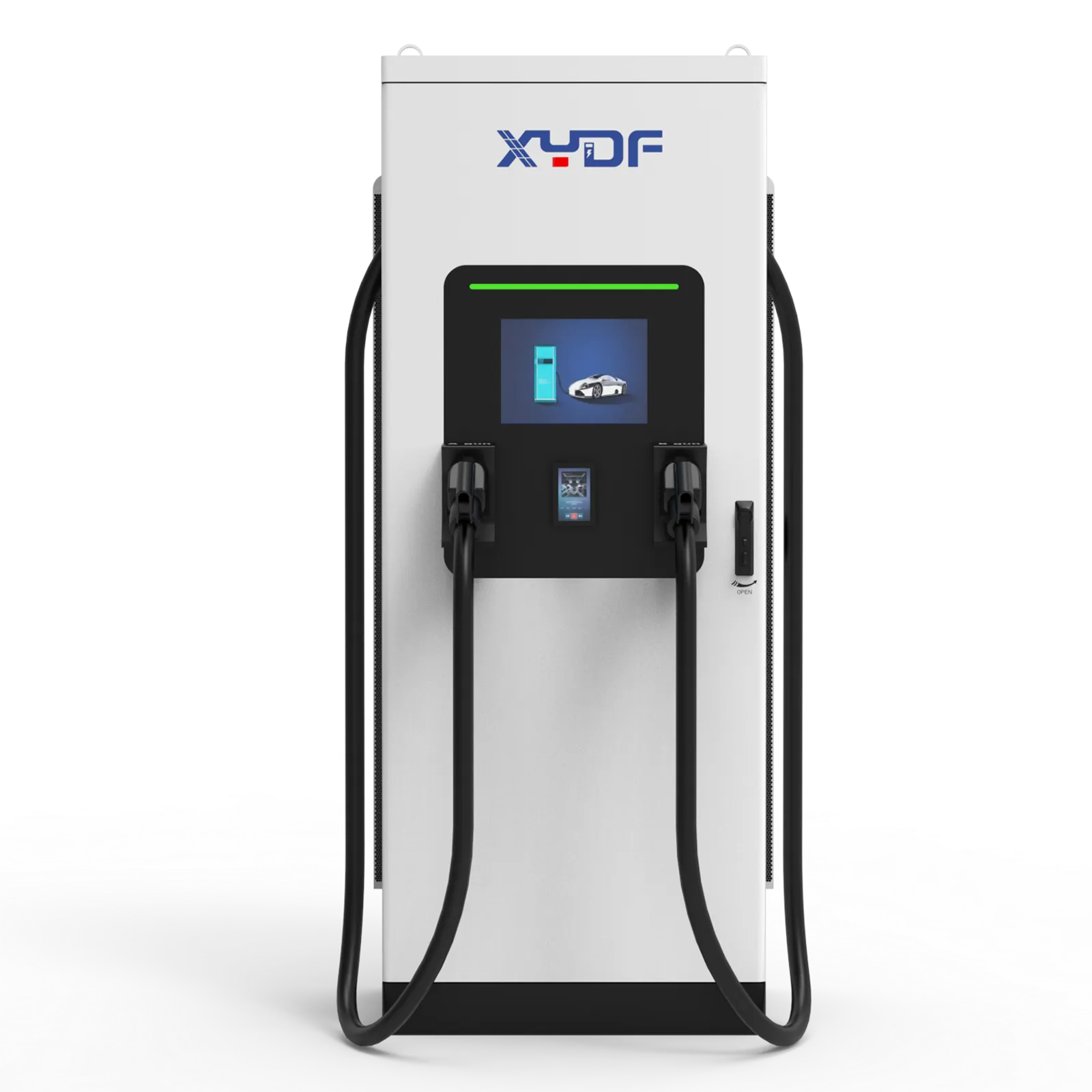
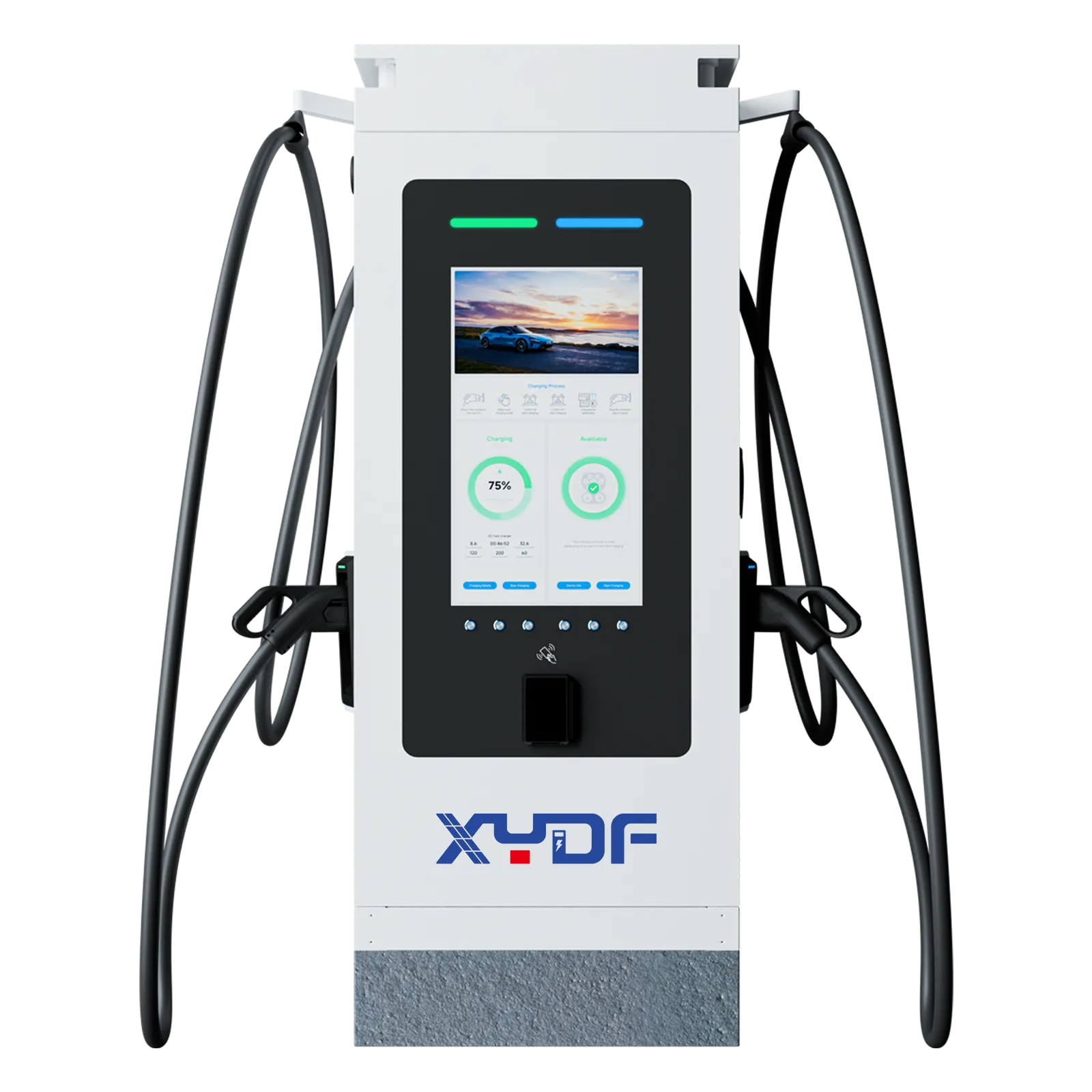
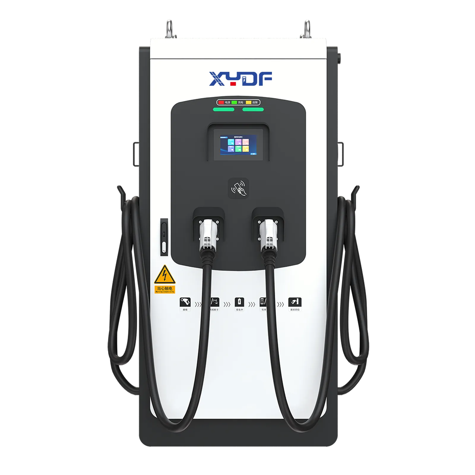
The first selection variable is the charging architecture. IEC 62955 concerns Mode 3 charging equipment; it is not a blanket rule for every EV supply system. Browse the AC charging equipment range و DC fast-charging equipment range as different equipment categories, then request the protection documentation for the actual model.
ال IEC 62955:2018 public abstract (edition 1.0, published 12 March 2018) covers permanently connected AC Mode 3 equipment up to 440 V AC and 125 A at 50/60 Hz. These are standard-scope limits, not XYDF ratings. It distinguishes RDC-MD monitoring devices from RDC-PD protective devices; documentation must establish which category the offered arrangement addresses. This scope does not establish a Mode 4 protection design.
In DC fast charging, the station contains the power conversion equipment. The AC input, internal converter, isolation arrangement, DC output, and any insulation-monitoring functions need assessment within that design. An AC-side Type B RCD does not, by itself, demonstrate adequate DC-output protection. Equally, a Mode 3 RDC-DD solution must not be assumed suitable for a DC fast charger.
| Application or decision | What to establish | أدلة للطلب |
|---|---|---|
| Mode 3 AC charger with integrated DC detection | Whether the adopted rules accept the detector arrangement with the specified RCD | IEC 62955 scope, circuit diagram, switching function, and installation instructions |
| AC charger without documented DC detection | Whether suitable Type B protection or another permitted arrangement is required | Charger instructions, circuit assessment, and protective-device ratings |
| Multi-outlet commercial installation | Individual protection requirements, shared leakage, and upstream coordination | Single-line diagram, circuit schedule, and commissioning plan |
| DC fast-charging station | AC-input and DC-output protection as separate but coordinated functions | IEC 61851-23 documentation and manufacturer-specific protection architecture |
| Replacement or retrofit | Compatibility with existing wiring, protective devices, and available board space | Existing installation records and updated verification results |
Compare total installed cost rather than component price alone. Include additional board equipment, integration work, test access, documentation, and maintenance procedures. An inexpensive detector can become a costly choice if its disconnection function is unclear; a more expensive protective device can still be unsuitable if its ratings or upstream coordination are wrong.
Commissioning: Test the Protection Path, Not Just the Button
The built-in test button is useful, but it does not prove the entire installation. Verification under the applicable electrical installation rules should combine visual inspection, required electrical tests, and the charger’s functional checks. IEC 60364-6 provides the general installation-verification framework; the adopted edition and local requirements determine the test schedule.
Use an installation tester that supports the actual RCD type and required waveforms. For an RDC-DD function, confirm that the instrument can perform the manufacturer-prescribed DC test; a basic AC-only RCD tester cannot establish its DC response. An EVSE adapter can provide access and charging-state simulation, but it is not automatically a residual-current test source.
Where the approved procedure requires them, record ramp-test operating current and time-test results using the specified waveform and test level. Do not substitute a single universal trip time for the limits applicable to the device and installation. Also confirm that fault detection stops charging and disconnects the conductors required by the design.
Make each test record traceable to the applicable procedure or report reference and revision, the tested hardware configuration, and the acceptance criterion used. That traceability permits meaningful review without inventing universal thresholds.
Document protective-conductor continuity, relevant insulation and earthing checks, device identification, instrument details, and the charging-state conditions used during tests. Insulation testing must follow the equipment instructions to avoid damaging connected electronics. Preserve the results against each circuit and outlet so that later maintenance can distinguish an installation defect from an equipment fault.
Standards, Regional Requirements, and Procurement Checks
IEC standards define different parts of the problem. IEC 60364-7-722 addresses EV supply installations; IEC 62955 addresses RDC-DD equipment for Mode 3 charging; IEC 62423 adds Type F and Type B RCD requirements. IEC 61851-1 covers general conductive charging equipment requirements, while IEC 61851-23 addresses DC EV supply equipment. None of these titles alone establishes that a particular charger is certified.
Regional requirements depend on the adopted electrical code, its edition, amendments, supply system, intended installation, and approval route. A solution accepted under one code framework may need different evidence elsewhere. Require documents that identify the exact model and assessed configuration, not a generic statement that the product “meets IEC.” Unsupported claims can cause redesign, rejected inspection, and delayed energization.
Match the offered model and hardware revision to its conformity documentation and test report. Require the wiring diagram and installation manual to identify the actual supply-opening device and specified upstream RCD, rather than accepting evidence for a different configuration.
Before placing an order, settle four questions:
- Which residual-current arrangement does the adopted code require or permit for this charging architecture?
- Which functions are inside the charger, and which protective devices must the installer supply?
- What model-specific test reports, conformity documents, and wiring instructions support the arrangement?
- How will commissioning verify detection, disconnection, and upstream coordination?
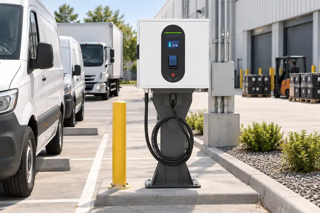
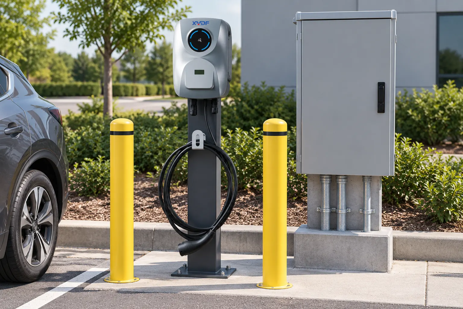
For an XYDF equipment enquiry, use the commercial AC charger product page as a starting point, then request documentation for the quoted configuration. Do not infer its residual-current arrangement, certifications, or protection settings from the product category or power rating.
أسئلة متكررة
What is the difference between RCD-DD and a Type B RCD for EV chargers?
An RDC-DD provides a dedicated DC residual-current detection function, with disconnection provided by its specified assembly or associated switching arrangement. A Type B RCD provides residual-current protection covering smooth DC and other specified waveforms. Compare the complete arrangement, including any required Type A RCD, rather than treating the detector as a standalone equivalent.
When does an EV charger require Type B residual-current protection?
Type B protection is needed when the applicable rules or equipment instructions require it, including situations where a permitted alternative DC-protection arrangement is absent or unsuitable. Check the charging architecture, adopted code, and charger documentation together. The presence of an unspecified “leakage sensor” is not enough to approve an alternative.
Can RCD-DD replace a Type B RCD in every installation?
No. A compliant Type A plus RDC-DD arrangement can be a permitted option for relevant AC charging installations, but that does not make it universal. DC fast-charging architecture, upstream equipment, and regional requirements need their own assessment.
What DC leakage current can an RCD-DD detect?
The widely used protection arrangement is associated with 6 mA smooth DC detection under the IEC 62955 framework. That figure is not a claim that every device trips at exactly 6 mA under every test condition. Obtain the model’s operating limits, response times, test conditions, and conformity evidence before specifying it.
How should residual-current protection be tested during EVSE commissioning?
Use an appropriate RCD or installation tester, with EVSE test access where required, following the adopted verification rules and manufacturer procedures. Verify the relevant waveforms and the resulting disconnection, not only the built-in test button. Record circuit-specific results and any required functional tests.
Which protection arrangement is best for AC charging and DC fast charging?
For AC charging, assess Type B against a permitted Type A plus RDC-DD arrangement using the documented equipment design. For DC fast charging, assess the AC input and DC output within the station’s protection architecture. There is no single device choice that proves both systems compliant.
المراجع
- IEC 62955: residual direct-current detecting devices for Mode 3 charging.
- IEC 62423: additional requirements for Type F and Type B RCDs.
- IEC 60364-7-722: supplies for electric vehicles.
- IEC 60364-6: verification of electrical installations.
- IEC 61851-23: DC electric vehicle supply equipment.
Choose a Verified Arrangement
The useful distinction is simple: detection identifies a fault; the complete protection arrangement must disconnect it correctly. Choose between Type A plus RDC-DD and Type B only after the code requirements, equipment documentation, and commissioning method agree.
مراجعة XYDF charging products for the required application, then اتصل بـ XYDF with your circuit design and protection requirements. Request the model-specific evidence before finalizing the installation specification.