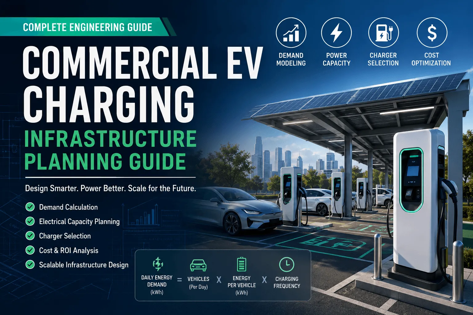
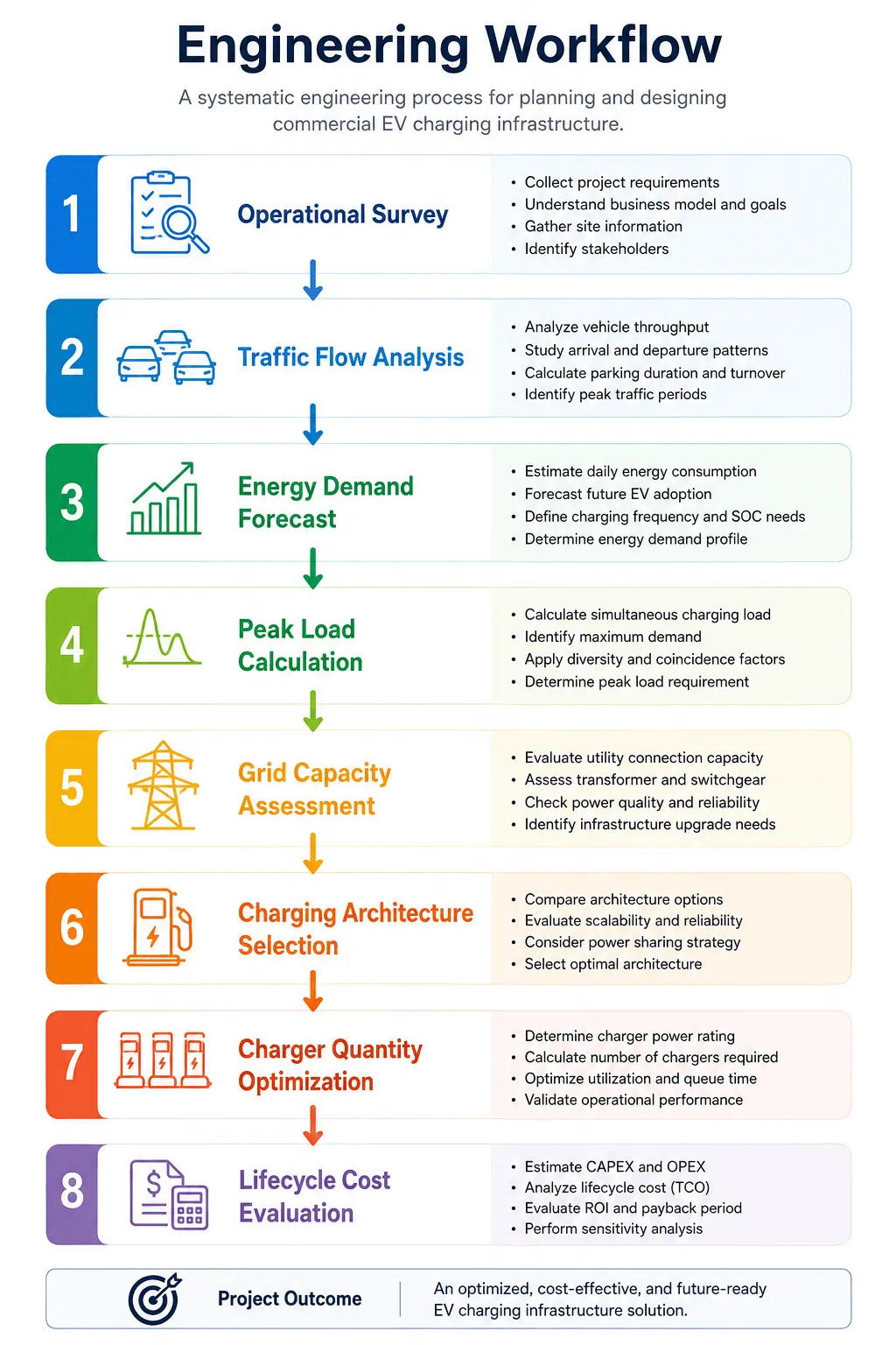
Commercial EV charging infrastructure is a long-term engineering investment rather than a standalone equipment purchase. Successful projects begin with operational demand forecasting, electrical infrastructure assessment, charging architecture selection, capacity modeling, interoperability planning, lifecycle cost analysis and supplier evaluation. This guide provides a structured engineering framework that enables project owners, fleet operators, commercial property developers and procurement teams to make technically sound and financially sustainable decisions.
Engineering Decision
Determine charging demand using operational data, traffic flow and energy consumption models before selecting charger types or power ratings.
Many commercial EV charging projects fail to achieve expected utilization or return on investment because infrastructure planning begins with equipment selection instead of demand analysis.
Charging demand directly influences:
Demand analysis should therefore become the first engineering task in every commercial charging project.
Commercial charging infrastructure should follow five fundamental engineering principles.
Charging capacity must be determined by operational demand rather than equipment availability.
Electrical systems should be designed for peak charging demand instead of average daily consumption.
Grid capacity and electrical infrastructure define charger selection—not the reverse.
Electrical distribution systems should reserve sufficient capacity for phased expansion over the next 5–10 years.
Engineering decisions should minimize total lifecycle cost instead of initial procurement cost.
Before calculating charging demand, project planners should first identify the operational scenario because different business models produce fundamentally different charging behaviors, utilization rates and investment objectives.
| Category | Typical Applications | Engineering Considerations |
|---|---|---|
| Fleet Charging | Logistics, delivery, municipal fleets | High daily utilization, predictable charging windows |
| Destination Charging | Hotels, resorts, tourist attractions | Long parking duration, lower charging power |
| Workplace Charging | Office buildings, business parks | Employee charging, daytime load management |
| Public Charging Network | Urban charging hubs | High vehicle turnover, dynamic utilization |
| Retail Charging | Shopping centers, supermarkets | Short dwell time, mixed AC/DC deployment |
| Bus Depot Charging | Public transportation | High-capacity DC charging, overnight scheduling |
| Logistics Hub Charging | Distribution centers | Continuous operation, fleet optimization |
Engineering Insight
Selecting the wrong business scenario often results in oversized infrastructure or insufficient charging capacity.
Vehicle type determines charging duration, battery capacity and charger power requirements.
| Vehicle Type | Typical Battery Capacity | Recommended Charging Power |
|---|---|---|
| Passenger EV | 50–90 kWh | 7–22 kW AC / 60–120 kW DC |
| Commercial Van | 70–120 kWh | 60–180 kW DC |
| Light Truck | 100–200 kWh | 120–240 kW DC |
| Heavy-duty Truck | 300–600 kWh | 350 kW+ |
| Electric Bus | 250–500 kWh | 240–480 kW DC |
Engineering Insight
Vehicle mix is one of the most important inputs when determining charger quantity and charging architecture.
Operational data forms the foundation of engineering calculations.
| Parameter | Why It Matters |
|---|---|
| Vehicle Throughput | Determines charger demand |
| Arrival Rate | Predicts queue formation |
| Departure Rate | Defines charging window |
| Parking Duration | Determines AC or DC charging suitability |
| Charging Frequency | Influences daily energy demand |
| Vehicle Turnover | Measures infrastructure utilization |
| Queue Length | Indicates service performance |
| Simultaneous Charging Ratio | Determines peak electrical load |
| Charger Utilization Rate | Influences ROI |
Engineering Insight
Instead of asking “How many chargers should I buy?”, engineers should first ask “How many vehicles require charging simultaneously?”
Energy demand determines electrical infrastructure requirements.
| Engineering Parameter | Application |
|---|---|
| Battery Capacity | Daily energy demand |
| State of Charge (SOC) | Charging duration estimation |
| Daily Energy Consumption | Grid capacity planning |
| Peak Charging Demand | Transformer sizing |
| Charging Window | Load scheduling |
| Maximum Demand | Utility connection |
| Demand Diversity Factor | Load optimization |
| Coincidence Factor | Infrastructure utilization |
| Power Factor | Electrical system efficiency |
Engineering Insight
Energy demand modeling is the basis for transformer sizing, switchgear selection and feeder design.
Commercial charging infrastructure should satisfy both engineering and financial objectives.
| Financial Indicator | Engineering Impact |
|---|---|
| CAPEX | Infrastructure investment |
| OPEX | Operating cost |
| Target ROI | Charger utilization target |
| Charging Revenue | Business model selection |
| Electricity Tariff | Charging strategy |
| Government Incentives | Project feasibility |
| Future Expansion | Infrastructure reservation |
Physical site conditions frequently determine project feasibility more than equipment specifications.
This section determines the amount of power that can be brought to the site and how that energy is distributed:
Grid Capacity: The maximum available capacity the upstream grid can supply to the site. This is often the primary bottleneck for constructing high-power fast-charging stations.
Transformer Capacity: The capacity of existing on-site transformers—or the potential for capacity expansion—directly determines how many units can operate simultaneously.
Switchgear (High/Low Voltage Distribution Cabinets): Critical equipment for controlling, protecting, and isolating the power system; its physical space and current ratings limit the addition of new circuits.
Distribution Panel: The terminal power distribution unit; it is necessary to assess whether there are sufficient spare circuit slots (breaker spaces) and adequate load-bearing capacity.
Cable Routing: The path taken by cables from the power distribution room to the terminal equipment. Factors such as soil conditions, existing underground utilities, and paved surfaces affect route length and construction complexity, directly impacting costs.
Available Land: The actual, usable net area of the site where equipment, transformers, and auxiliary facilities can be legally installed.
Parking Layout: For EV projects, parking space design (perpendicular, angled, or heavy-vehicle bays) and dimensions must ensure smooth vehicle entry and allow charging cables to easily reach the vehicle’s charging port.
Auxiliary support conditions required to ensure long-term, stable system operation and regulatory compliance:
Communication Network: The availability of on-site cellular signals (4G/5G) or wired broadband coverage. This is crucial for equipment connectivity, backend management (e.g., OCPP communication), and payment processing.
Cooling Requirements: High-power, high-voltage equipment (such as superchargers and transformers) generates significant heat during operation; the site must provide adequate ventilation or sufficient space for specialized chilled-water or air-cooling units. Fire Protection: Compliance with local fire safety regulations (e.g., fire separation distances, provision of fire-extinguishing equipment, and safe evacuation routes), particularly mandatory fire safety requirements for high-voltage and battery-related facilities.
Drainage: Drainage capacity for outdoor sites or underground garages. Measures must be in place to prevent accumulated rainwater from submerging the bases of electrical equipment, thereby ensuring electrical safety.
This section covers the mainstream physical charging interfaces (connectors) and electrical characteristic standards across different global regions:
CCS1 (Combined Charging System 1): The mainstream DC fast-charging standard in the North American market, based on the AC Type 1 (SAE J1772) interface.
CCS2 (Combined Charging System 2): The mainstream DC fast-charging standard in Europe and most other regions, based on the AC Type 2 (Mennekes) interface.
NACS (North American Charging Standard): A charging standard for North America (originally Tesla’s proprietary interface); it has now been standardized by SAE as J3400 and has become the dominant standard in the North American market.
GB/T (Chinese National Standard): The EV charging standard for the Chinese market (covering AC GB/T 20234.2 and DC GB/T 20234.3; currently evolving toward the next-generation ChaoJi standard).
SAE J1772: The North American standard for single-phase AC charging interfaces (Type 1), widely used for residential slow-charging stations.
IEC 61851: The overarching standard for EV conductive charging systems, defining charging modes (Modes 1–4), safety requirements, and basic control pilot signals (PWM).
IEC 62196: Specifies dimensional interchangeability and performance requirements for charging plugs, socket-outlets, vehicle inlets, and vehicle connectors (defining the underlying specifications for the physical interfaces mentioned above).
ISO 15118: The communication protocol between the vehicle and the charging station (V2G / vehicle-to-charger communication). It supports advanced features such as Plug & Charge, smart charging management, and bidirectional charging (V2G).
OCPP 2.0.1 (Open Charge Point Protocol): An open communication protocol between charging stations and a central management system (cloud backend). Version 2.0.1 brings significant enhancements to security, device management, and support for ISO 15118.
OCPI (Open Charge Point Interface): A roaming protocol between Charging Point Operators (CPOs) and e-Mobility Service Providers (eMSPs) that enables EV users to charge and settle payments across different charging networks.
Engineering Insight
Design Highlights:
Designing projects and developing products based on open standards (such as OCPP, ISO 15118, etc.) effectively reduces reliance on specific vendors (avoiding vendor lock-in) and greatly simplifies future system upgrades, capacity expansion, and cross-platform interoperability.
| Parameter | Typical Value | Engineering Purpose |
|---|---|---|
| Daily Charging Sessions | 20–1,000+ | Charger quantity |
| Vehicle Throughput | 50–5,000/day | Capacity planning |
| Peak Demand | 100 kW–5 MW | Transformer sizing |
| Parking Duration | 30 min–10 h | Charger selection |
| Charger Utilization | 20–70% | ROI analysis |
| Daily Energy Consumption | 200–20,000 kWh | Grid assessment |
| Simultaneous Charging Ratio | 20–80% | Electrical load calculation |
| Scenario | Recommended Architecture | Design Priority |
|---|---|---|
| Logistics Fleet | Centralized DC Charging | Fleet turnaround |
| Bus Depot | High-power DC Charging | Overnight charging |
| Office Building | AC Charging | Employee convenience |
| Hotel | Destination AC Charging | Long dwell time |
| Shopping Mall | AC + DC Hybrid | Customer experience |
| Public Charging Hub | Distributed Fast Charging | Maximum utilization |
Commercial EV charging demand analysis is not simply a calculation of charger quantity. It is the engineering foundation that determines electrical infrastructure design, charging architecture, capital investment, operational efficiency and long-term scalability. Projects that prioritize operational analysis before equipment selection consistently achieve higher charger utilization, lower lifecycle costs and greater flexibility as EV adoption grows.
Q1: Why should demand analysis be conducted before selecting charging equipment?
Answer: Many projects fail because they start with equipment selection rather than operational data analysis. Charging demand (derived from vehicle throughput, arrival rates, and parking duration) directly dictates critical infrastructure sizing, including charger quantity, power ratings, transformer capacity, and initial CAPEX. Prioritizing demand analysis ensures higher charger utilization and avoids costly oversized or under-capacity installations.
Q2: What are the risks of ignoring “Simultaneous Charging Ratio” during peak hours?
Answer: Designing electrical systems based on average daily consumption rather than peak demand is a common engineering mistake. Ignoring the simultaneous charging ratio during peak hours usually leads to severe transformer overloading, tripped switchgear, or localized grid failure. Engineers must ask “How many vehicles require charging simultaneously?” to accurately size transformers and design load-scheduling strategies.
Q3: How do site constraints like “Grid Capacity” act as a bottleneck for commercial charging projects?
Answer: Physical site conditions frequently determine project feasibility more than equipment. Grid capacity—the maximum available power specifications the upstream grid can supply—is often the primary bottleneck for high-power fast-charging stations. If the existing grid or transformer capacity is insufficient and cannot be expanded, the project cannot support advanced DC fast chargers regardless of the equipment specifications.
Q4: Why is a “Modular Expansion” approach recommended for electrical distribution design?
Answer: EV adoption scales over time. Designing infrastructure only for current demand without reserving expansion capacity is a critical mistake. Electrical distribution systems should follow the “Infrastructure Before Equipment” principle, reserving sufficient space and capacity (such as spare breaker spaces in distribution panels) for phased, seamless expansion over the next 5–10 years.
Q5: What is the significance of adopting open standards like OCPP 2.0.1 and ISO 15118?
Answer: Selecting proprietary communication protocols limits future interoperability and leads to vendor lock-in. Designing around open standards ensures compatibility between vehicles, chargers, and cloud networks. Specifically, ISO 15118 enables advanced features like Plug & Charge and bidirectional charging (V2G), while OCPP 2.0.1 enhances security and backend device management, greatly simplifying future system upgrades.
Q6: How should charging architectures be matched to different business scenarios?
Answer: Planners must match the architecture to the parking behavior of the scenario. For instance, Logistics Fleets and Bus Depots require Centralized/High-power DC Charging to ensure fast vehicle turnaround or overnight scheduling. Conversely, Office Buildings and Hotels should deploy AC Charging because employees and guests have long parking durations (dwell times), making daytime load management more practical and cost-effective.
Q7: Why must “Demand Charges” be included in lifecycle cost calculations?
Answer: Engineering decisions should minimize total lifecycle cost (LCO) instead of initial procurement cost (CAPEX). Relying solely on equipment cost and simple energy consumption while ignoring utility demand charges—tariffs based on peak power draw—leads to severely warped ROI models. Factoring in demand charges allows engineers to implement peak-shaving and load-optimization strategies to minimize operational expenses (OPEX).
Q8: What auxiliary site systems are critical for maintaining safety and compliance?
Answer: Beyond the chargers themselves, three auxiliary systems are critical:


 Xinya Dongfang Electricity Technology Co., Ltd.


 CCS2 EV Connector")