 Xinya Dongfang Electricity Technology Co., Ltd.



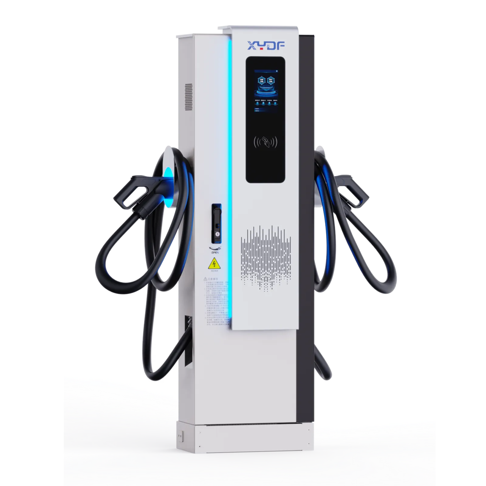
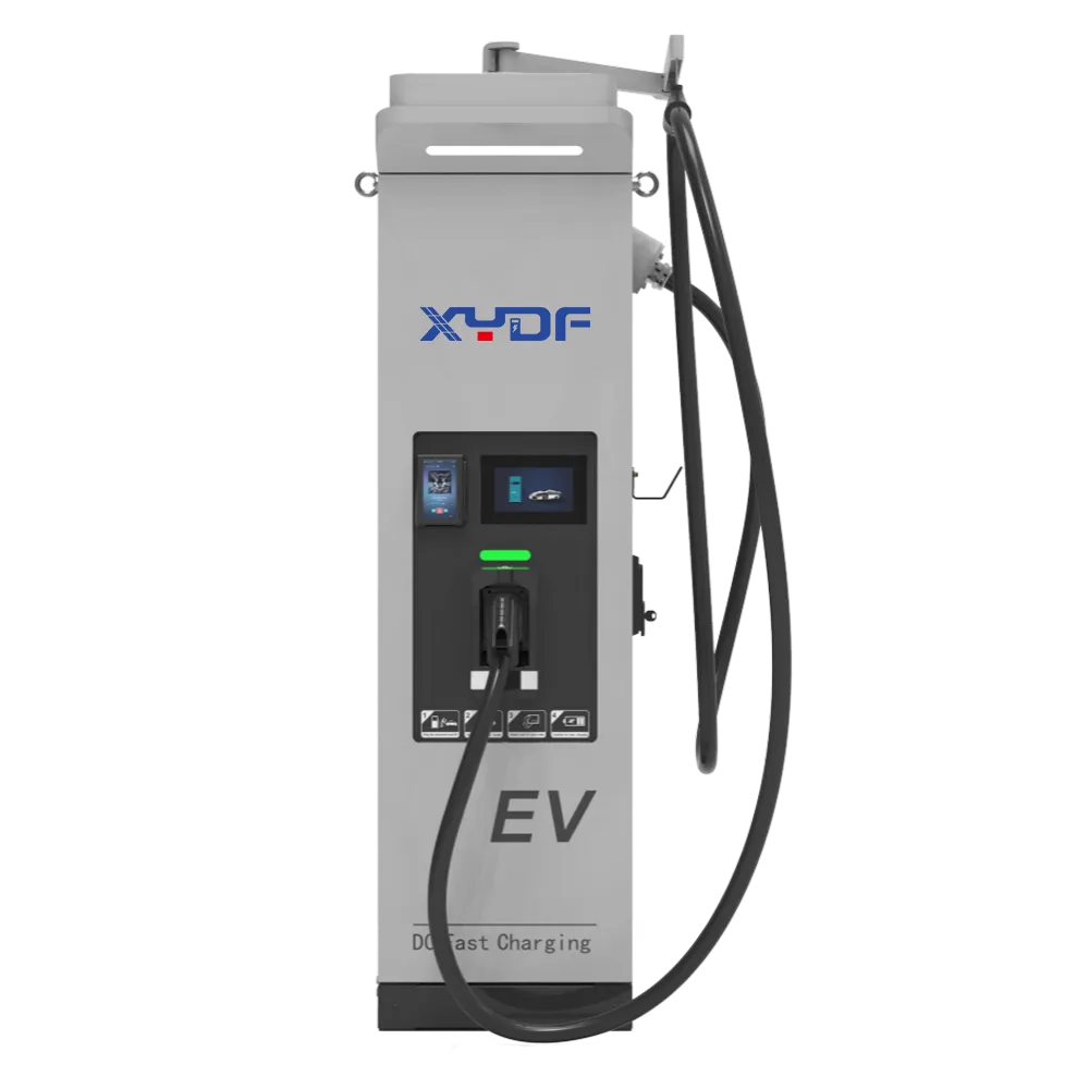
An integrated solar, storage and EV charging project succeeds or fails at the system boundary. PV modules, a battery and chargers can each meet their own specifications while the complete site still exceeds its import limit, exports when it should not, or leaves vehicles short of energy at departure. The design therefore has to begin at the point of common coupling (PCC), with the site’s time-series load, vehicle duty, utility conditions and operating priorities visible in one model.
Summary: Treat a integrated PV + ESS + EV charging site as one electrical and control system. Use at least 12 months of interval data where available, distinguish battery power in kW from usable energy in kWh, and test import, export, reserve and communications-loss modes before handover. A 600 kW charger nameplate is not a 600 kW grid requirement, but a battery cannot be sized from charger power alone. Grid-parallel operation also does not imply backup: islanding needs a defined critical-load boundary, transfer and protection design, black-start sequence and approval by the utility and authority having jurisdiction (AHJ).
Define the electrical and control boundary first
The minimum boundary normally includes the utility meter and PCC, transformer, main switchboard, non-EV building or process loads, PV inverter, BESS power conversion system (PCS), chargers, protection, site meters, communications and the energy management system (EMS). If backup is required, add the transfer device, critical-load board, grounding arrangement and every auxiliary load needed to start and cool the battery. Omitting any of these elements produces an incomplete load balance.
At every interval, the EMS must reconcile four quantities: non-EV site demand, vehicle charging demand, PV output and BESS charge or discharge. The PCC then sees the residual. Import and export limits are separate contractual constraints; a zero-export setting is not a substitute for anti-islanding protection, and permission to export does not guarantee a valuable export tariff.
AC-coupled and DC-coupled architectures
In an AC-coupled site, the PV inverter, bidirectional PCS and AC or DC chargers meet on an AC bus. This is often practical for retrofits and phased expansion because assets can retain separate protection and maintenance paths. A DC-coupled architecture can share a DC bus among PV, battery conversion and DC charging. It may remove a conversion stage in a selected power path, but it concentrates responsibility for isolation, pre-charge, DC fault protection, controls and future compatibility.
Efficiency must be stated for a defined path and operating point. For example, if a 100 kWh PV input passes through a 96% PV inverter, one battery path represented by 94%, and a 97% charger, the result is about 87.5 kWh at the vehicle, not 84 kWh. If 94% applies separately to both battery charge and discharge, the result is about 82.2 kWh. Procurement documents should identify the measurement boundary, auxiliary consumption, temperature and part-load condition instead of multiplying unrelated brochure peaks.
The grid interface sets hard design constraints
Record the contracted import limit, permitted export, demand-meter interval, reactive-power obligation, protection settings and the utility’s change process. IEEE 1547 is an important US framework for distributed-energy-resource interconnection and interoperability, but it applies only where adopted or required; the serving utility’s agreement and local rules govern the project. Other markets use their own grid codes and conformity routes.
Translate each utility condition into a witnessed test. An export cap, for example, needs a PCC measurement, a response-time requirement, a control margin, a fallback on stale data and a test with a fast PV increase and falling site load. A software setpoint without a defined meter, latency and safe state is not an enforceable boundary.
Size from interval loads and departure energy
Energy-management claims should identify which load is flexible and which service obligation is not. Align vehicle departure energy, solar production, storage state, building demand, tariff intervals, and grid limits in one time-based model; then define fallback behaviour when renewable output, communications, or storage availability changes. Research guidance can explain managed charging, but it cannot substitute for site telemetry and a tested control policy. For the public planning context, see NREL managed electric vehicle charging guidance; the site-specific acceptance record still controls the final decision.
Start with measured site data at the same or finer resolution than the tariff demand window. Fifteen-minute data may support an early study, but one-minute or event data can be necessary where charger steps, process starts or protection coordination matter. The site’s commercial EV charging load-profiling guide provides a complementary data checklist.
| Input | Minimum planning detail | Design question it answers |
|---|---|---|
| Existing load | Interval kW/kvar, seasonal peaks, process starts and outage history | How much PCC and feeder headroom exists by time? |
| Vehicle duty | Arrival SoC, energy required, departure time, connector and accepted power | Which sessions are flexible and which are deadline-critical? |
| PV resource | Weather-year production, orientation, clipping, soiling and curtailment | How much production coincides with charging or battery headroom? |
| Battery limits | Continuous kW, usable kWh, SoC window, efficiency, auxiliaries and derating | How large a deficit can be covered, and for how long? |
| Commercial rules | Energy tariff, demand window, export value, penalties and escalation assumptions | Which dispatch constraint has measurable value? |
Keep battery kW and usable kWh separate
Battery energy storage for EV charging must address both the largest instantaneous shortfall and its duration. A useful interval equation is: required BESS kW = charger kW + non-EV load kW – PV kW – allowed grid-import kW, with negative results set to zero. Usable energy is the time integral of that positive shortfall, adjusted for the defined discharge efficiency and required end-of-event reserve. Nominal battery energy then depends on the warranted usable SoC window, temperature, ageing allowance and where energy is measured.
A 1 MW/1 MWh battery can theoretically deliver rated power for one hour before reserve, derating and auxiliaries are considered. It cannot support 500 kW for six hours. Conversely, a high-kWh battery with a low-power PCS may have enough stored energy but still fail to hold the PCC limit during a sharp charging step. The battery sizing checklist for EV charging stations expands these distinctions.
A corrected illustrative calculation
Retain the original planning case as an illustration, not a recommendation: a warehouse has a 600 kW daytime base load, a 1.2 MW process peak, 20 vans needing 45 kWh each between 18:00 and 06:00, a proposed 750 kW PCC cap and 600 kW of charger nameplate power.
- Vehicle energy is 20 x 45 kWh = 900 kWh. At an illustrative 92% charger-and-cable path efficiency, upstream energy is about 978 kWh.
- Average upstream charging demand across the full 12-hour window is only about 81.5 kW. The actual power requirement depends on arrivals, departure deadlines, each vehicle’s acceptance curve and the dispatch schedule.
- At the 600 kW base load, the 750 kW cap leaves 150 kW for charging. If chargers request 600 kW and PV is zero, storage, load curtailment or charger throttling must cover 450 kW. No defensible battery kWh value can be calculated until the duration of that deficit is known.
- The stated 1.2 MW process peak already exceeds the proposed PCC cap by 450 kW before EV charging. The study must establish whether that peak is coincident, controllable, supplied by BESS or excluded from the proposed operating window.
- For a separate illustrative PV target of 1,200 kWh per day, four equivalent full-sun hours and an 80% aggregate yield give 1,200 / (4 x 0.80) = 375 kWp. Location, weather dataset, array geometry, clipping and export restrictions must replace those assumptions for a real project.
Run the balance across a representative year and stress it with cloudy periods, clustered arrivals, a charger outage, low initial battery SoC, temperature derating and an unexpected process start. A model should report unserved vehicle energy, not hide it by assuming every requested charging setpoint was delivered.
Write control modes, fallback states and backup scope
Dynamic EV charging load management allocates available power while respecting electrical ratings and departure commitments. A workable priority order is: protect people and equipment; hold utility import and export limits; preserve any contracted resilience reserve; meet deadline-critical vehicle energy; use available PV; then serve discretionary sessions. The owner should approve this order because changing it can change both fleet readiness and the financial result.
| Mode | Primary objective | Acceptance evidence |
|---|---|---|
| Normal grid-parallel | Meet vehicle needs within equipment and PCC limits | Time-aligned PCC, charger, PV and BESS trends |
| Import limiting | Keep demand below a contracted threshold | Step-load test with defined margin and response time |
| Zero export or export cap | Prevent or limit reverse flow at the PCC | PV ramp and load-drop test, including meter or network loss |
| PV capture | Charge vehicles or BESS when otherwise-curtailed PV is available | SoC, charger-priority and curtailment records |
| Reserve preservation | Maintain energy for a defined backup event | Minimum-SoC enforcement and operator override log |
| Communications loss | Reach a deterministic safe operating state | Disconnected-meter, EMS and charger test cases |
Use timestamps and quality flags. A stale meter value must not become a fresh zero. Define charger fallback setpoints, battery ramp limits, recovery delays and who may override them. OCPP supports charger-to-management communication; ISO 15118 covers vehicle-to-charger communication and certificate-based functions in compatible implementations. Neither label alone proves end-to-end interoperability, so firmware profiles, backend behavior and offline cases belong in factory acceptance testing (FAT).
Make cybersecurity part of the operating design
Segment charger, BESS, EMS and enterprise networks according to the site’s risk assessment. Identify every remote connection, restrict administrative access, use certificate-based encrypted transport where the selected systems support it, and log configuration, command and firmware changes. The contract should assign responsibility for certificates, credential rotation, vulnerability notices, patches, rollback and service access after the warranty period.
OCPP 1.6J and OCPP 2.0.1 do not expose identical security and transaction behavior. State the required protocol edition, security profile, smart-charging messages, offline authorization, transaction recovery and log retention, then test the exact charger, backend and firmware combination. For ISO 15118 functions, include the selected edition, vehicle support and certificate trust chain. A menu option or datasheet logo is not evidence that the complete workflow operates.
Grid-parallel storage is not automatically backup
Most commercial inverters are grid-following in normal operation and must cease energizing an unintended island. A backup or microgrid scope needs a grid-forming source, an approved separation method, grounding and neutral treatment, a protection study, critical-load segregation, black-start energy, auxiliary-power sequencing and a controlled reconnection. State whether EV chargers remain on, shed to a lower limit or disconnect during an outage.
Define backup as a service level: named loads, maximum kW, minimum duration, starting conditions and allowable transfer interruption. Reserve held for backup is then unavailable for peak shaving unless the operating policy explicitly releases it. Counting the same kWh for both guaranteed resilience and routine arbitrage overstates value.

Review safety, interconnection and maintainability by jurisdiction
Codes and standards have different roles. IEC 61851-1 covers general requirements for conductive EV supply equipment; the IEC 62196 series addresses plugs, socket-outlets, vehicle connectors and inlets; IEC 62477-1 addresses safety for power electronic converter systems. Citing one of these standards is not the same as showing that a specific model has been evaluated by an accepted conformity-assessment route.
In North America, NFPA 855 addresses installation of stationary energy storage systems. UL 9540 concerns an energy-storage system and equipment safety listing, while UL 9540A is a test method for evaluating thermal-runaway fire propagation. A UL 9540A report is not a product certification or a universal permission for reduced separation. The adopted code edition, battery chemistry and configuration, test evidence, fire engineering, emergency plan and AHJ decision control the site outcome.
Separate vehicles, pedestrians and high-energy equipment. Review impact protection, drainage, flood level, fire-service access, ventilation, gas detection where required, emergency isolation, cable management, working clearances and the path for replacing a battery module or charger power unit. The electrical review should also cover short-circuit duty, selectivity, earth-fault behavior, harmonics, power factor, surge protection, insulation monitoring where applicable and arc-flash labeling.
Design maintenance and end of life into the layout
Provide lockout/tagout points, visible isolation, service clearances, lifting routes and space to remove the largest replaceable assembly without blocking emergency access. Define critical spares such as contactors, fuses, filters, cables and network components from failure impact and lead time, not from a generic kit. Handover records should include protective-device settings, torque records, insulation-resistance results, thermal images, meter calibration and a component-level maintenance schedule.
Battery augmentation is a planned lifecycle action, not automatically a warranty event. The owner should know whether additional modules can be mixed with aged modules, whether PCS or enclosure capacity is reserved, and which party updates the controls and safety documentation. End-of-life planning must follow the destination market’s waste, transport and recycling rules. Include removal access, packaging responsibility, temporary storage and data disposal for networked equipment in the lifecycle scope.
Commission against requirements, not a demonstration script
FAT should verify the agreed register map or API, charger allocation, SoC limits, alarm handling, time synchronization, firmware versions and simulated meter failures. Site acceptance testing (SAT) should add actual protection settings, emergency stops, isolation, import and export limits, PV and BESS ramps, charger start/stop, communications loss, restoration and any approved islanding sequence.
Record test prerequisites, initial SoC, ambient conditions, meter locations, expected result, actual result, timestamps and unresolved defects. Store single-line diagrams, settings, declarations, applicable test reports, calibration records and software backups with the handover pack. The EV charging commissioning and handover guide provides a document-level follow-up.
Use operating data to protect the business case
The business case should compare a baseline without the project against at least two dispatch cases. State annual grid energy, PV production, on-site PV use, exports, curtailment, battery throughput, peak import, delivered vehicle energy, missed departure energy and charger availability. Tools such as NREL’s REopt can support scenario screening, but their inputs and constraints still need project verification.
Separate value streams so they are not double counted: avoided energy purchases, demand-charge reduction, export revenue, deferred grid work, charging revenue and quantified operational continuity. A deferred grid upgrade has value only if its cost and timing are documented. Demand savings require the model to reproduce the tariff’s exact averaging window and ratchet rules; see the site’s commercial peak-demand control guide for a focused treatment.
Include surveys, design, permits, civil work, canopy and structural work, transformer and switchgear changes, interconnection fees, PV, BESS, chargers, networking, commissioning and contingency in capital cost. Operating cost should include purchased energy, demand charges, software, communications, inspections, HVAC and standby energy, planned maintenance, spares, insurance, battery augmentation, component replacement and end-of-life obligations.
State the analysis period, discount rate, tariff escalation, utilisation ramp, weather year, degradation method, usable-energy warranty boundary, augmentation timing, tax or incentive assumptions and residual value. Test lower utilisation, clustered arrivals, a cloudy year, higher demand charges, delayed interconnection and an early replacement. Savings and payback remain site-specific; neither should be promised from equipment nameplates.
Minimum operating-data set
Retain time-aligned PCC import and export, non-EV load, PV output, BESS charge/discharge and SoC, charger setpoint and delivered kWh, session faults, availability, curtailment, alarms, control-mode changes and auxiliary consumption. Review performance after 30 and 90 days and across the first seasonal cycle. Compare the actual dispatch with the modeled reason for each setpoint change before attributing a gap to battery degradation.
Stage expansion around measured triggers
Reserve switchboard ways, communications capacity, addressing, transformer study space and a physically usable BESS augmentation area only where a later phase is credible. Define each expansion trigger in measurable terms, such as fleet count, recurring queue time, delivered energy, tariff change or a funded connection upgrade. Re-run protection, fault-duty and control studies when the trigger is reached; spare space does not prove the electrical system can accept added power.
For a multi-tenant park, name the site energy manager, charge-point operator and electrical responsible person. Agreements should say who owns interval data, who may change charging priorities, how a shared PCC or battery limit is allocated, and who communicates emergency curtailment. Publish reservation, idle-time, privacy and escalation rules to users. Ambiguous ownership can delay recovery even when every component remains functional.
Architecture comparison by operating objective
| Dimension | PV + AC-coupled BESS + AC/DC chargers | DC-coupled PV + BESS + DC chargers | Grid-only managed charging |
|---|---|---|---|
| Energy path | Modular AC bus with path-dependent conversion losses | Shared DC bus can remove selected conversions | Utility-to-charger path with no local generation or storage |
| Best fit | Retrofits, mixed charger types and phased expansion | High daytime DC demand where integrated control is justified | Sites with adequate connection capacity or little solar area |
| Import control | Strong when PCS kW, usable kWh and controls match the deficit | Strong when the common controller and DC protection are proven | Limited to scheduling, charger throttling and available grid headroom |
| Expansion | Broad equipment choice, but interfaces still require testing | DC bus voltage, protection and vendor interfaces can constrain additions | Simple locally, but later storage integration may require redesign |
| Backup potential | Only with designed grid-forming and transfer scope | Only with designed grid-forming and transfer scope | Charging normally stops with utility loss |
| TCO drivers | Interconnection, augmentation, software, conversions and civil work | DC protection, controls, specialist service and vendor dependence | Grid upgrades, energy tariff and demand charges |
No architecture is the universal winner. Compare all options with the same vehicle demand, weather year, tariff, import/export limits, reserve policy, degradation assumptions and availability target.
Configuration questions by application
| Application | Dominant operating pattern | Questions to settle | Evidence to request |
|---|---|---|---|
| Workplace or retail | Long dwell and daytime PV opportunity | Can flexible AC charging follow PV without harming access? | Parking turnover, accessibility review, utilisation and payment tests |
| Fleet depot | Predictable returns and hard departure deadlines | What energy is guaranteed by vehicle and shift? | Telematics, route schedule, dispatch simulation and SAT records |
| Industrial park | Large process loads and multiple tenants | Who owns the PCC limit, data and shared battery capacity? | Tariff, tenant rules, protection study and metering architecture |
| Highway charging | Short dwell and uncertain coincident DC demand | How are queues, derating and connector outages handled? | Arrival model, charging curves, thermal limits and availability records |
| Resilience-focused campus | Critical loads during a grid event | Which loads island, for how long and under whose authority? | Microgrid study, black-start test, fire plan and AHJ approval |
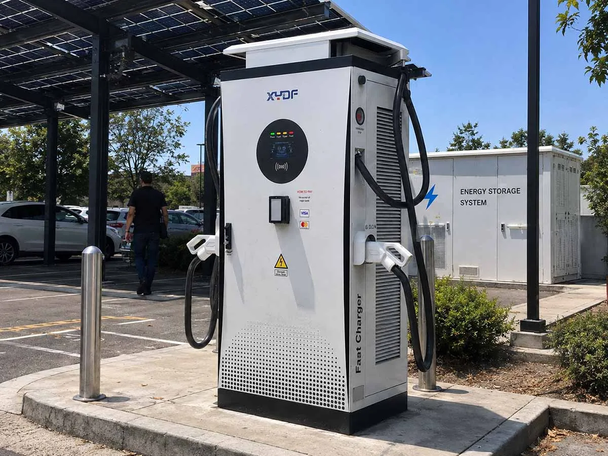
Five procurement gates before a purchase order
- Freeze the boundary: issue the single-line diagram, PCC conditions, measured load dataset, vehicle matrix, operating priorities, critical-load scope and expansion triggers.
- Validate the model: require interval results for PV, BESS SoC, charger allocation, PCC flow, losses, reserve and unserved vehicle energy, including degraded-year and sensitivity cases.
- Map compliance: assign each grid, electrical, fire, EMC, accessibility, metering and communications requirement to the responsible party and required evidence. Distinguish standards, test methods, listings, declarations and permits.
- Freeze interfaces and tests: identify firmware, OCPP and ISO 15118 profiles, meter protocol, fallback values, FAT/SAT scripts, cybersecurity controls, spares and defect-closeout rules.
- Approve lifecycle governance: name the data owner, operator, electrical responsible person, fire-response contacts and parties responsible for firmware, augmentation, recycling and periodic business-case review.
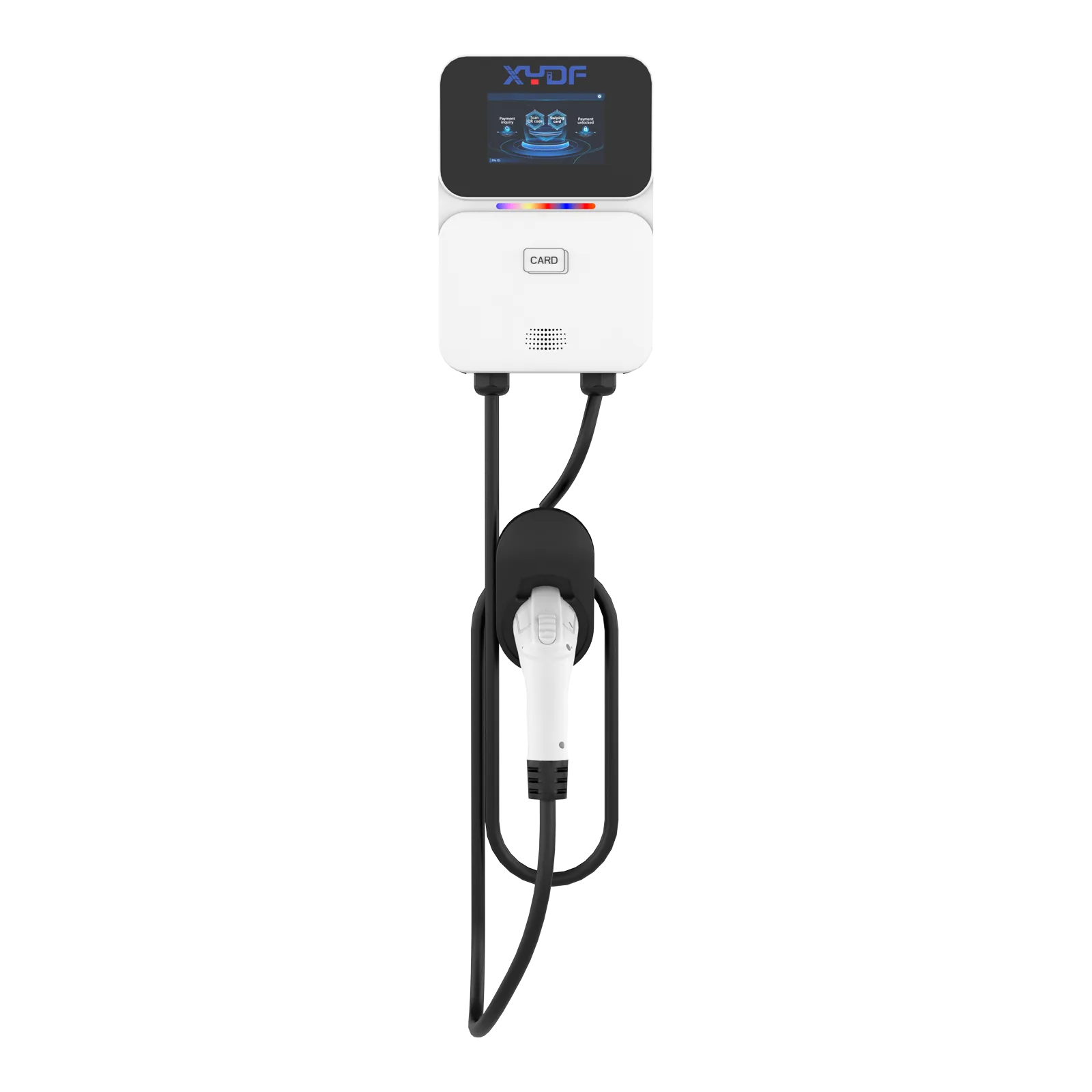
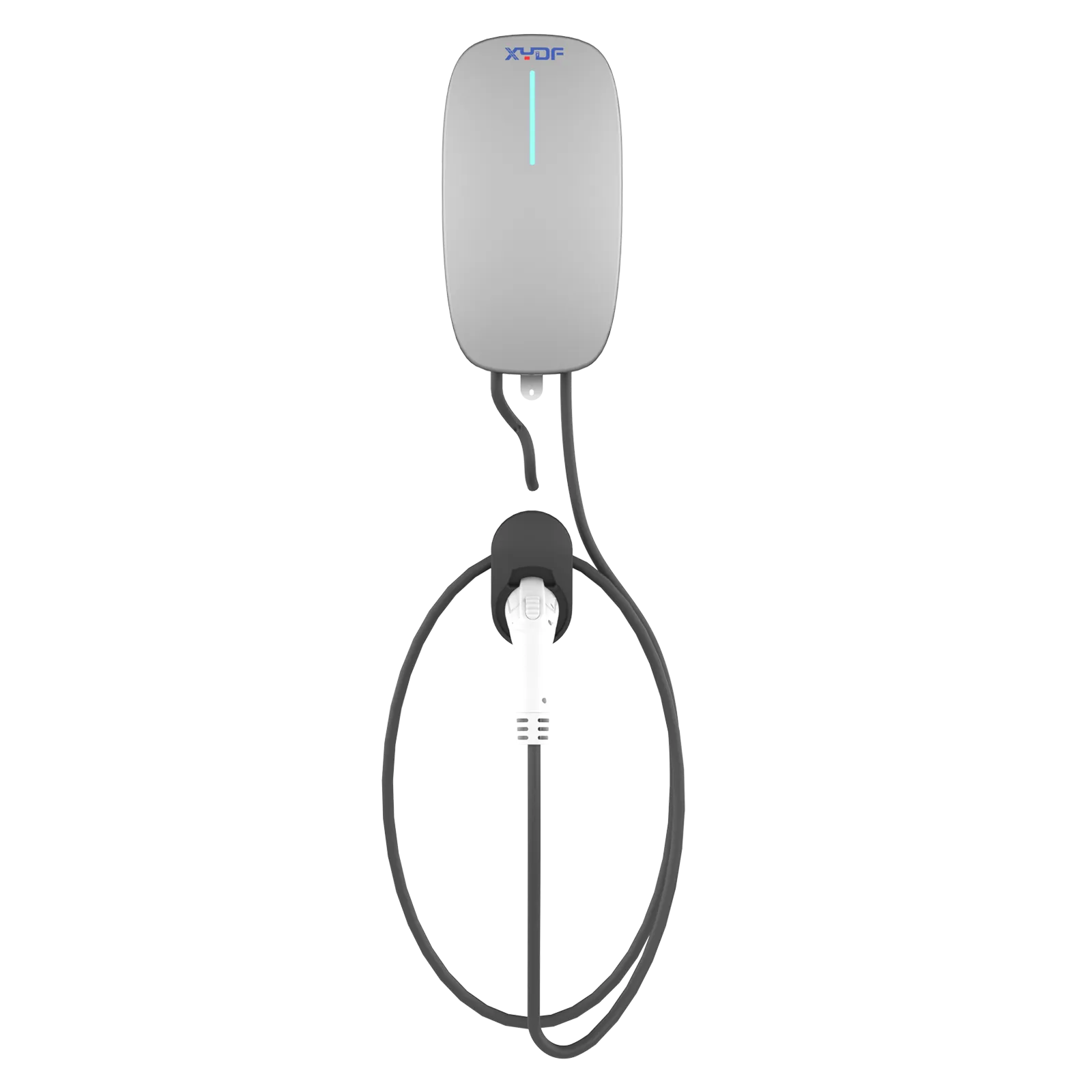
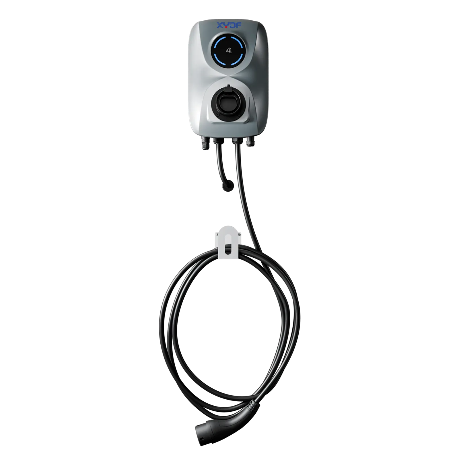
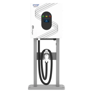
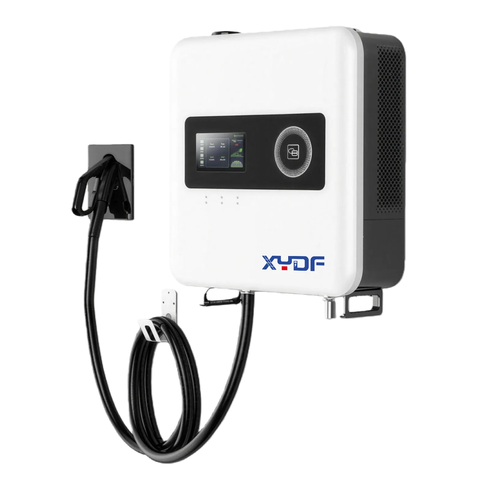
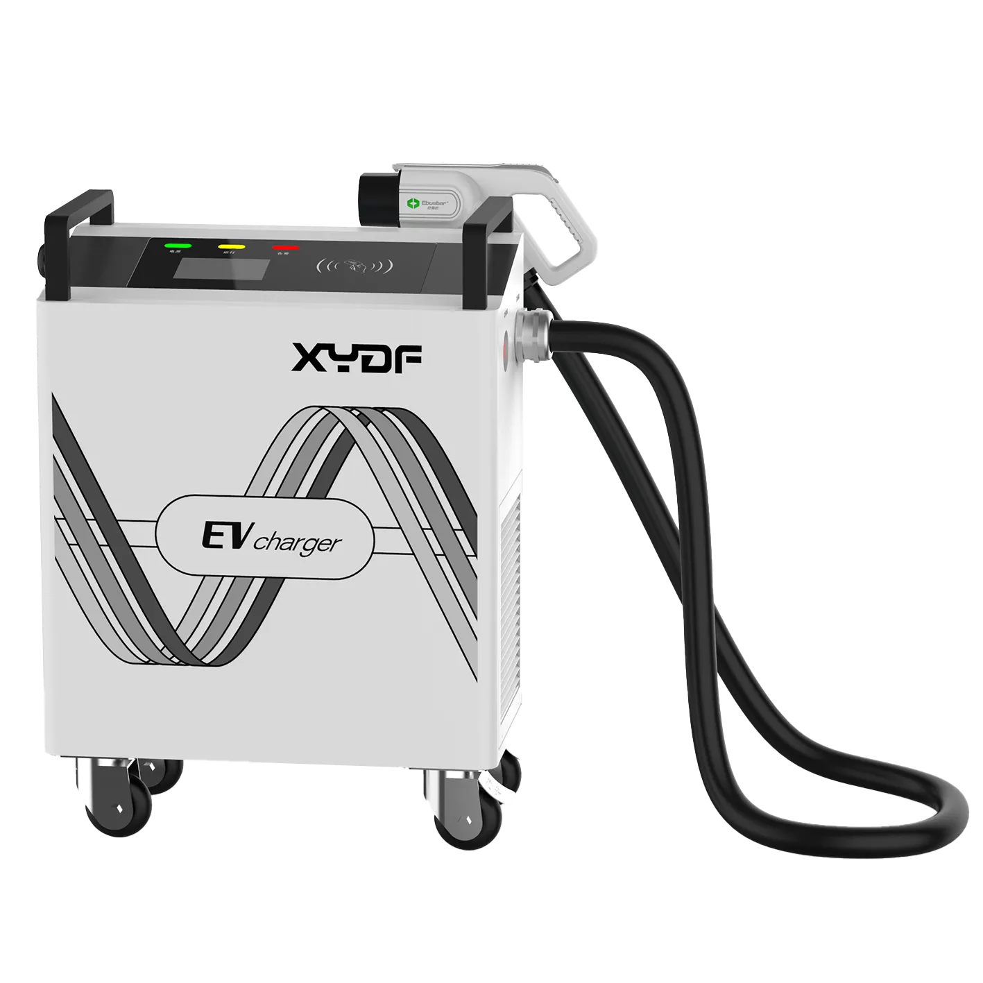
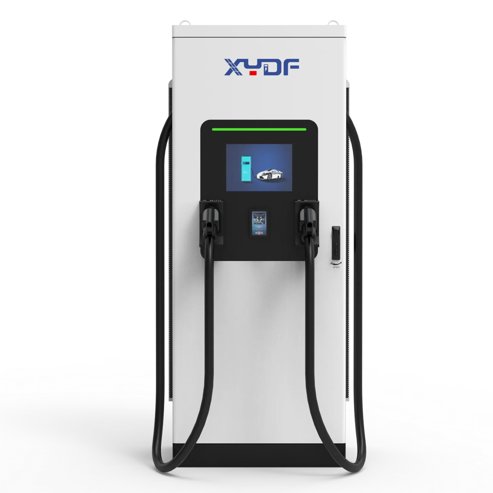
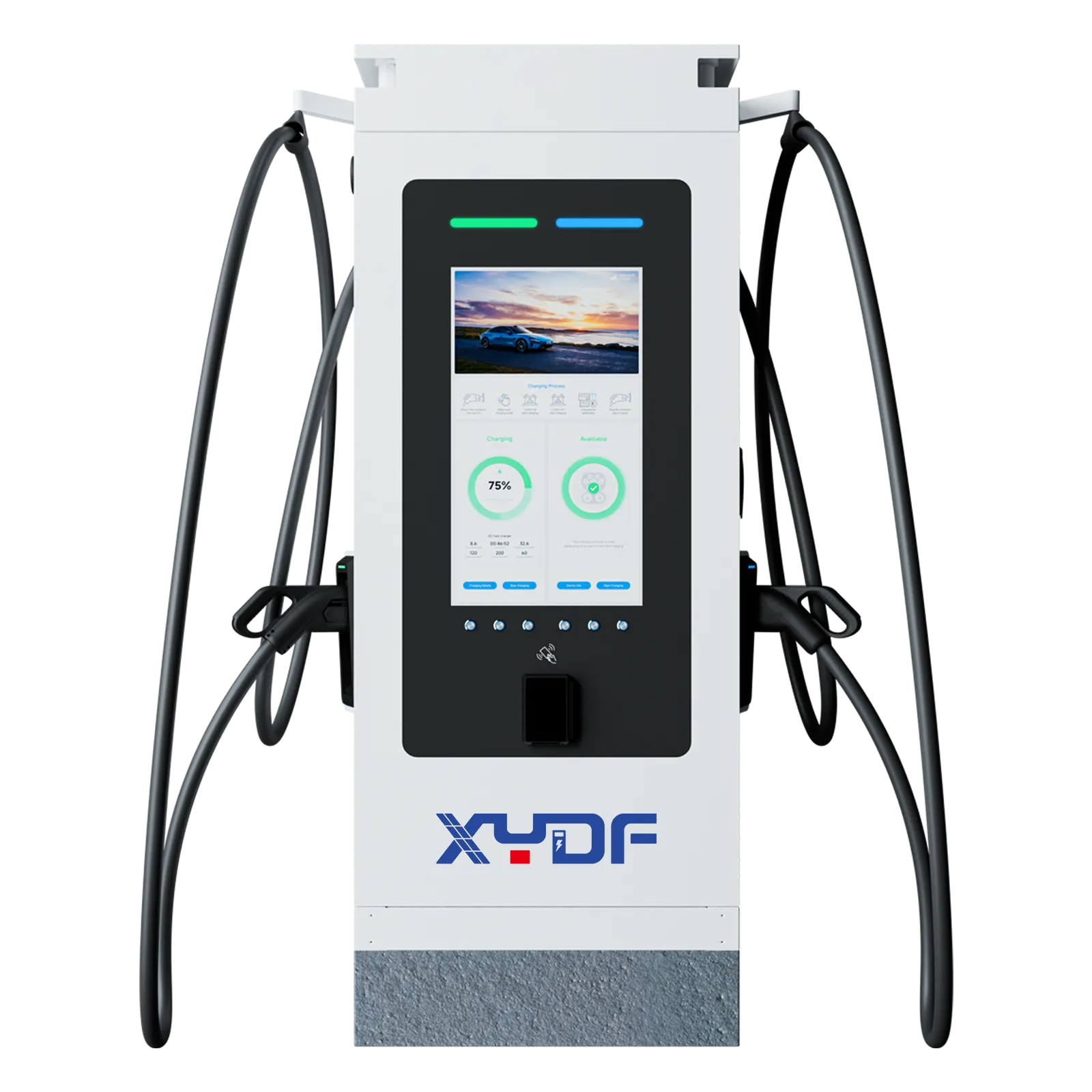
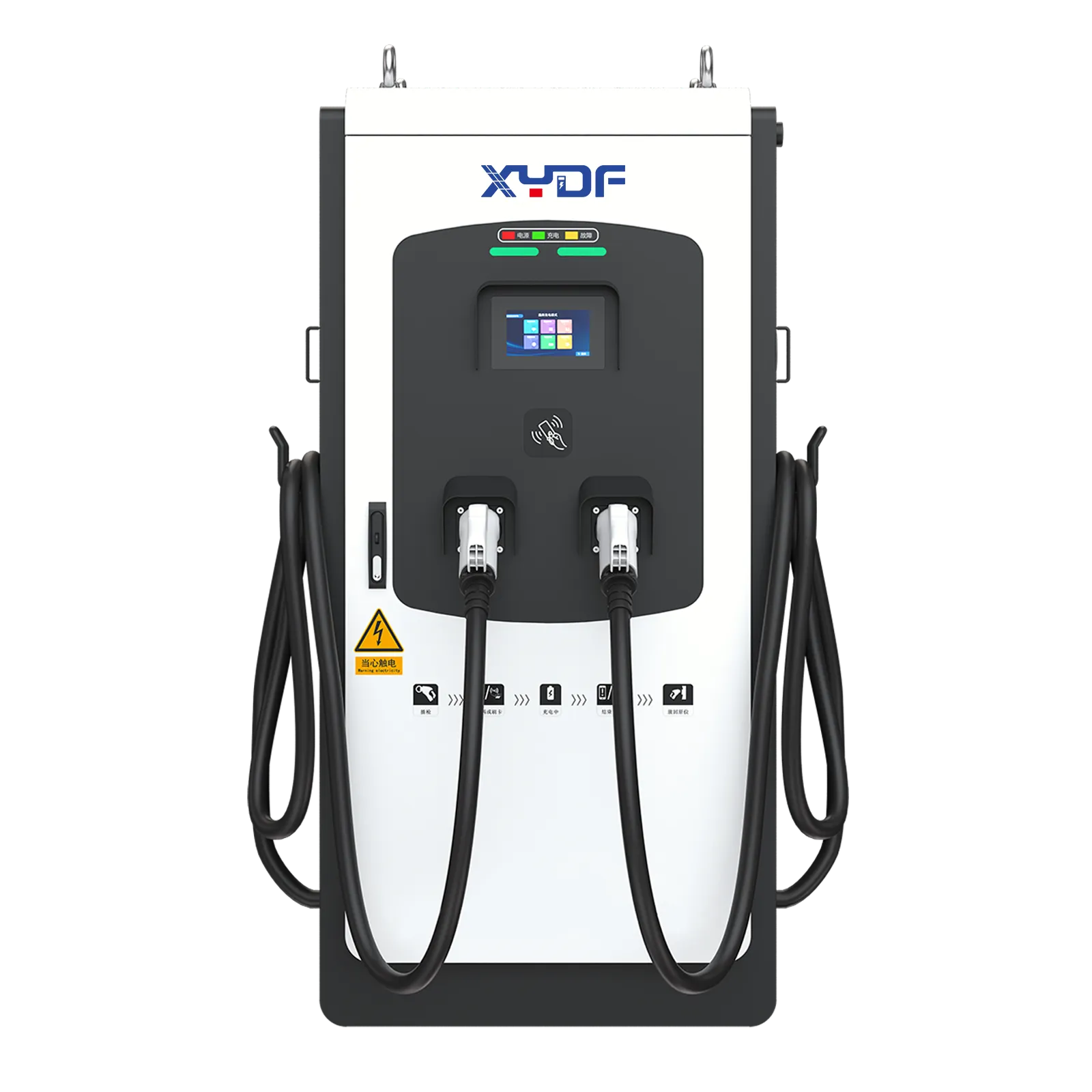
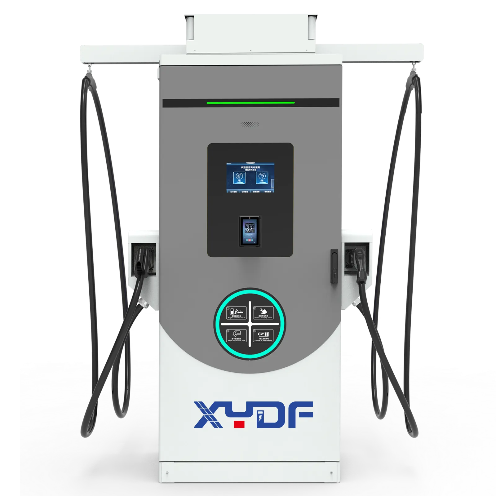
XYDF, also known as XYDF, can be evaluated as one configurable equipment and integration source within this process. Request the exact product scope, drawings, interface responsibility and model-specific evidence; independent designers, utilities and AHJs still determine project acceptance.
Frequently asked questions
How large should a battery be for a solar EV charging site?
Size kW from the largest modeled power shortfall and usable kWh from the duration of all positive shortfalls, then add only the reserve, ageing and operating margins that the duty requires. Use interval site load, vehicle energy and PV data; charger nameplate power alone cannot produce a defensible battery size.
Is AC coupling or DC coupling more efficient?
DC coupling can remove a conversion stage on selected PV-to-battery or PV-to-vehicle paths, while AC coupling often makes retrofits and phased expansion easier. Compare measured, path-specific efficiency at representative loads and temperatures, including auxiliaries, rather than one peak component value.
Can solar charging avoid all grid demand charges?
No. Clouds, nighttime charging, process loads, battery SoC and tariff rules can still create a billed peak. Model the exact demand interval and leave control margin for response delay and meter uncertainty.
Do OCPP and ISO 15118 guarantee Plug & Charge interoperability?
No. OCPP connects the charger with a management system, while ISO 15118 covers vehicle-to-charger communication and related certificate workflows in compatible implementations. Verify editions, profiles, backend support, certificate handling, vehicle support and offline behavior together.
Which fire standards apply to BESS at an EV charging site?
The answer depends on jurisdiction, adopted code edition, chemistry, energy, enclosure and site configuration. NFPA 855 and UL documents are widely used in North America, but the AHJ decides the required review and evidence; UL 9540A is a test method, not a blanket certification or permit.
What should be measured after commissioning?
Measure PCC import/export, non-EV load, PV output, BESS power and SoC, charger commands and delivered energy, missed departure energy, availability, faults, mode changes and auxiliaries on synchronized timestamps. Compare actual operation with the approved model after 30 days, 90 days and a full seasonal cycle.
How should an EV site verify a solar, storage, or load-management strategy?
Verify the strategy with time-aligned data for vehicle energy, solar output, storage state, building load, tariff periods, and departure requirements. Test low-solar, constrained-grid, communications-loss, and late-departure cases, then record whether the controller preserves the required vehicle energy before shifting flexible load. A dashboard screenshot is not a performance test.
References
- NREL, Battery Energy Storage for Electric Vehicle Charging Stations.
- NREL, REopt energy integration and optimization tool.
- IEC 61851-1:2017, Electric vehicle conductive charging system – Part 1: General requirements.
- IEEE 1547-2018, Standard for Interconnection and Interoperability of Distributed Energy Resources.
- NFPA 855, Standard for the Installation of Stationary Energy Storage Systems, and UL Solutions, UL 9540A Test Method for Battery Energy Storage Systems.
Design the energy journey before selecting the equipment list: define every boundary, model every interval and accept every operating mode against recorded evidence. For a documented solar EV charging solution review, share the load profile, vehicle schedule, PCC conditions, backup scope and destination market with the XYDF PV + ESS + EV charging team.