 Xinya Dongfang Electricity Technology Co., Ltd.


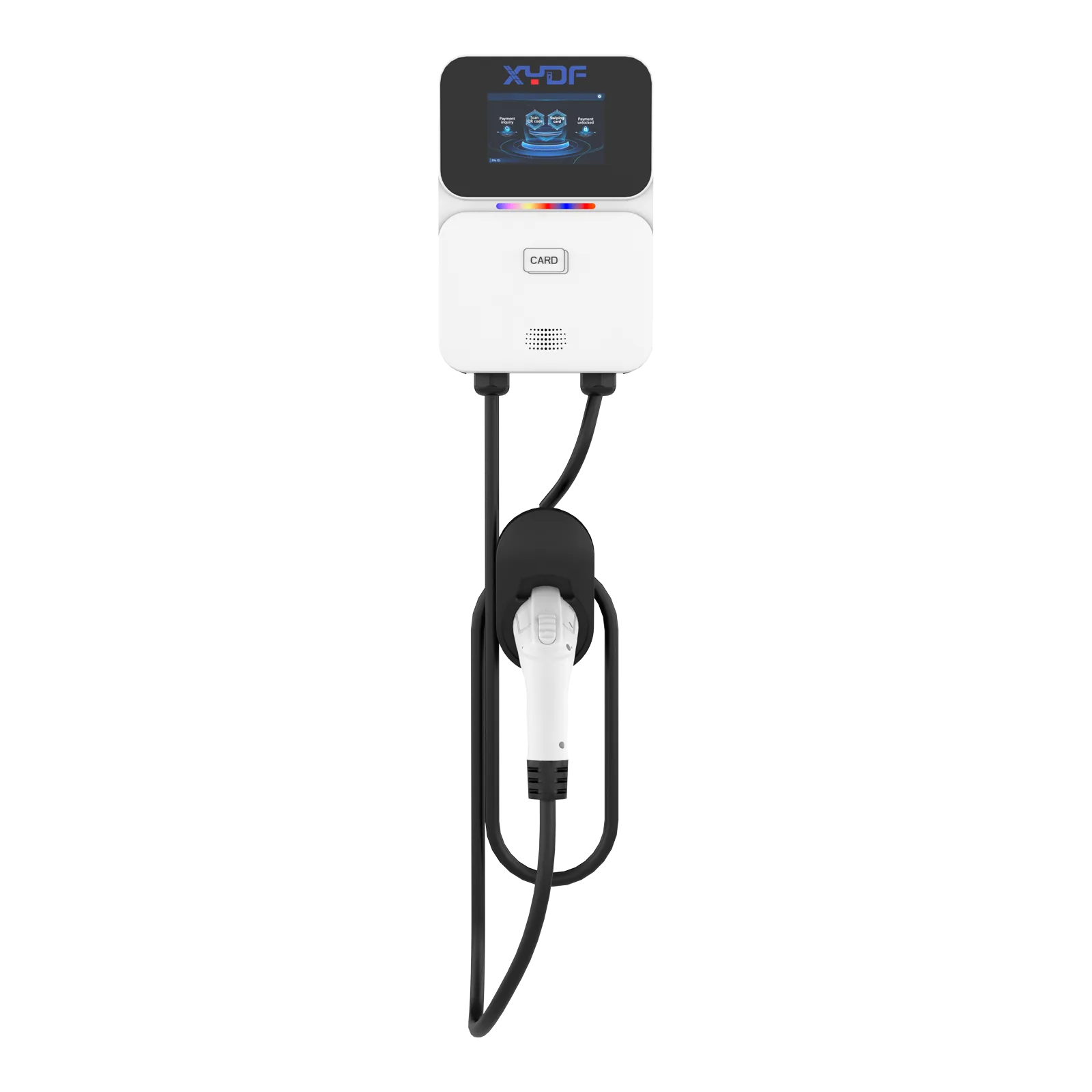
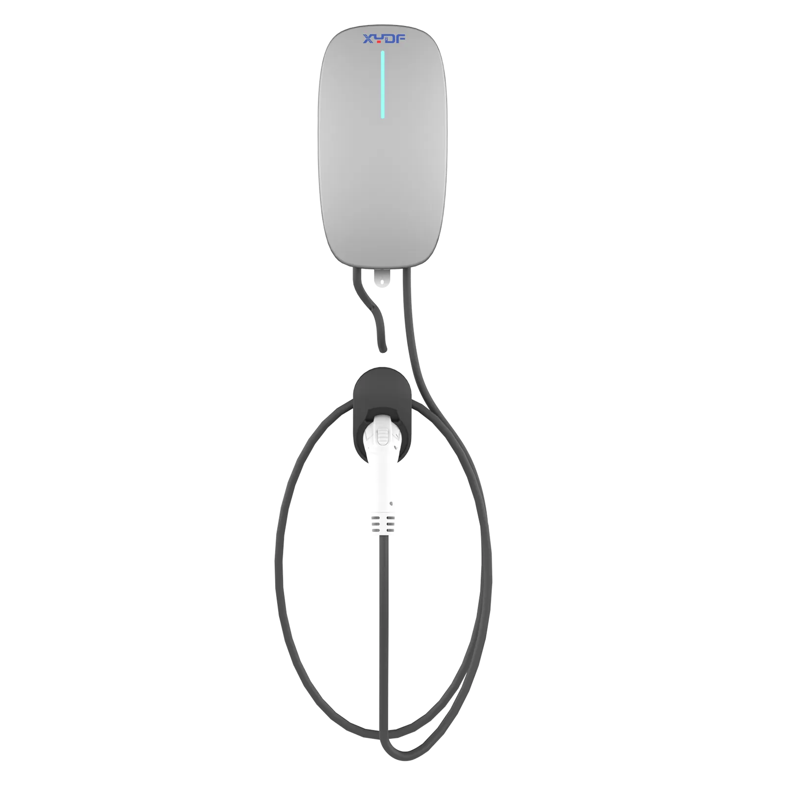
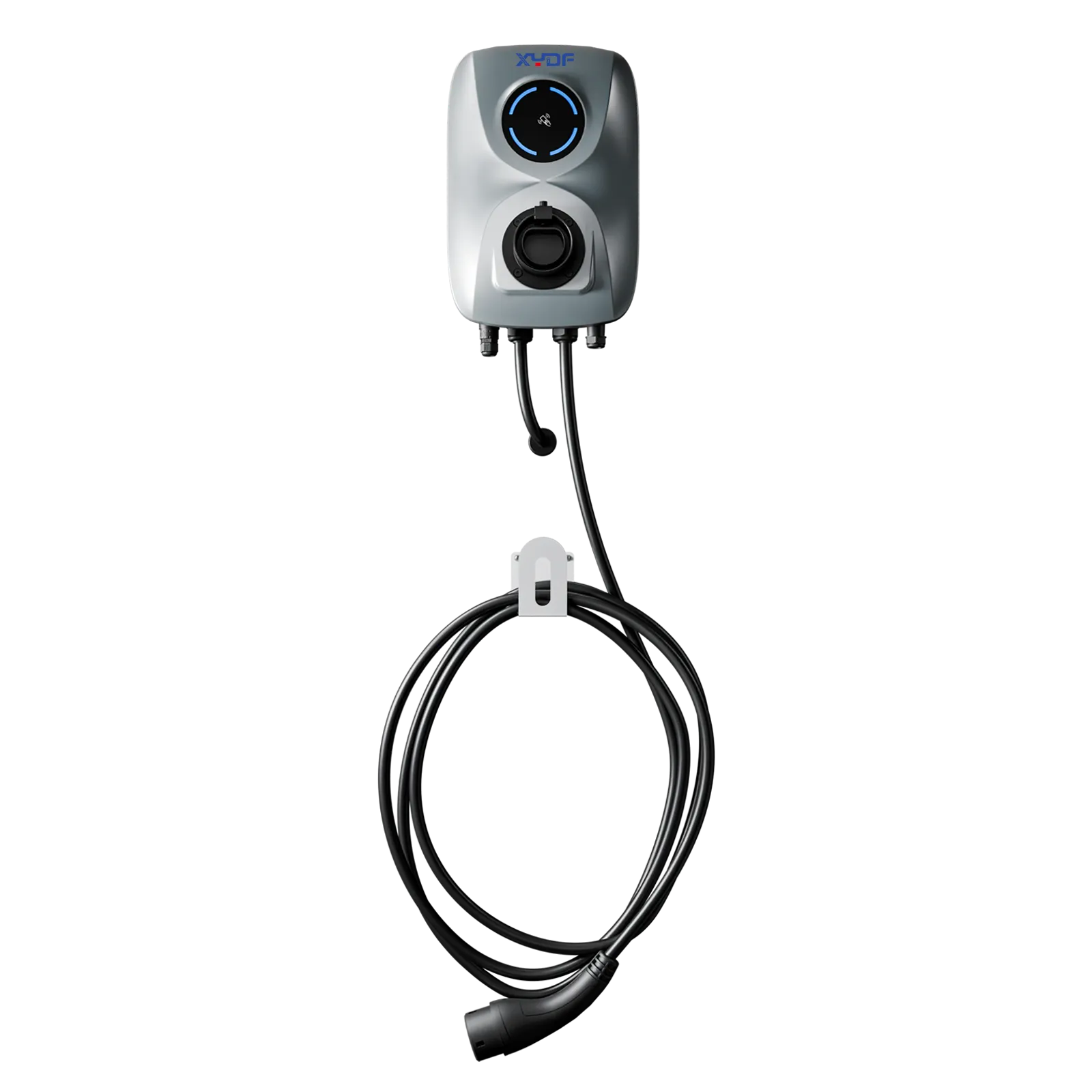
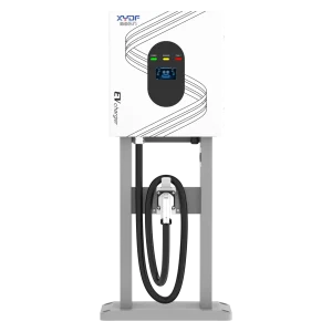

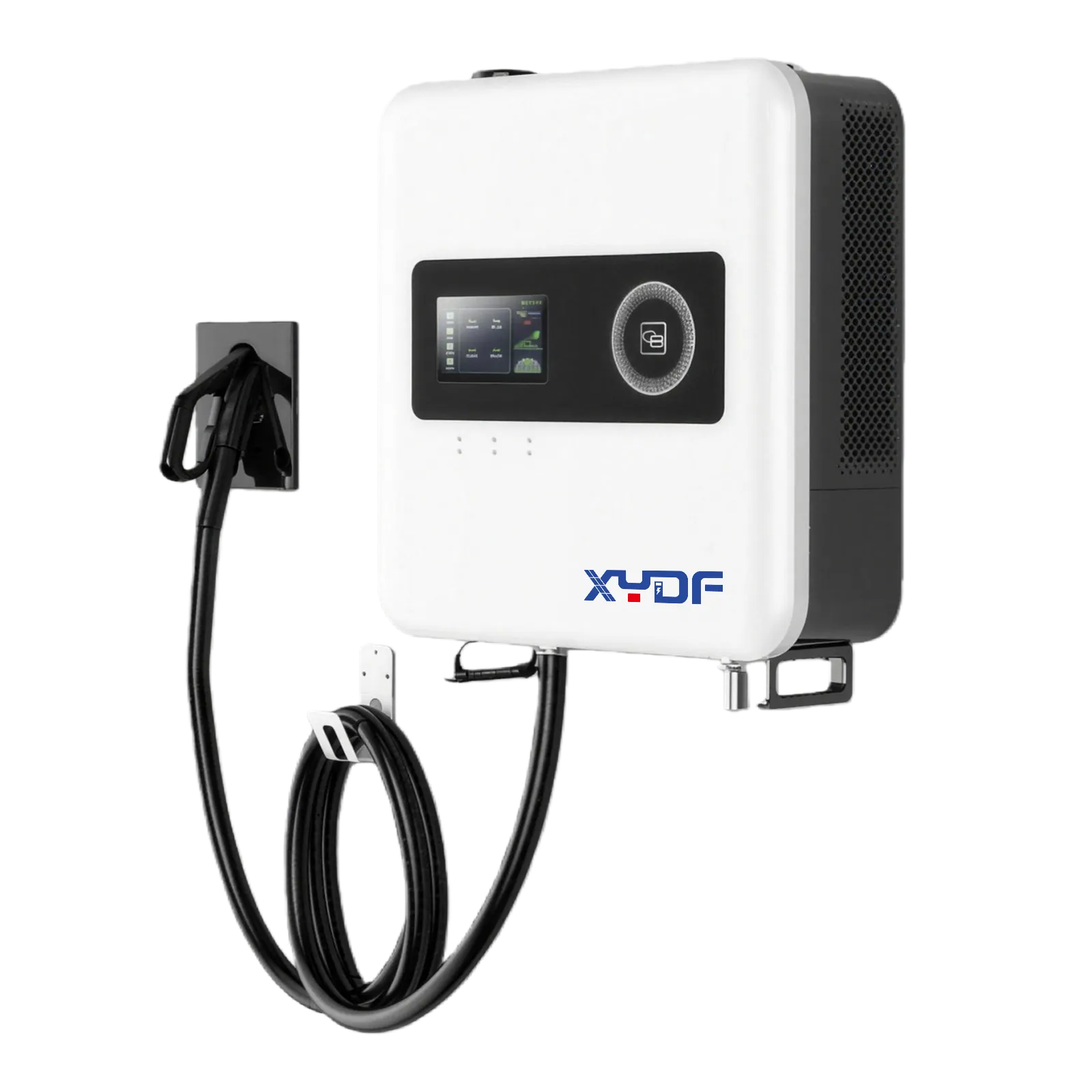
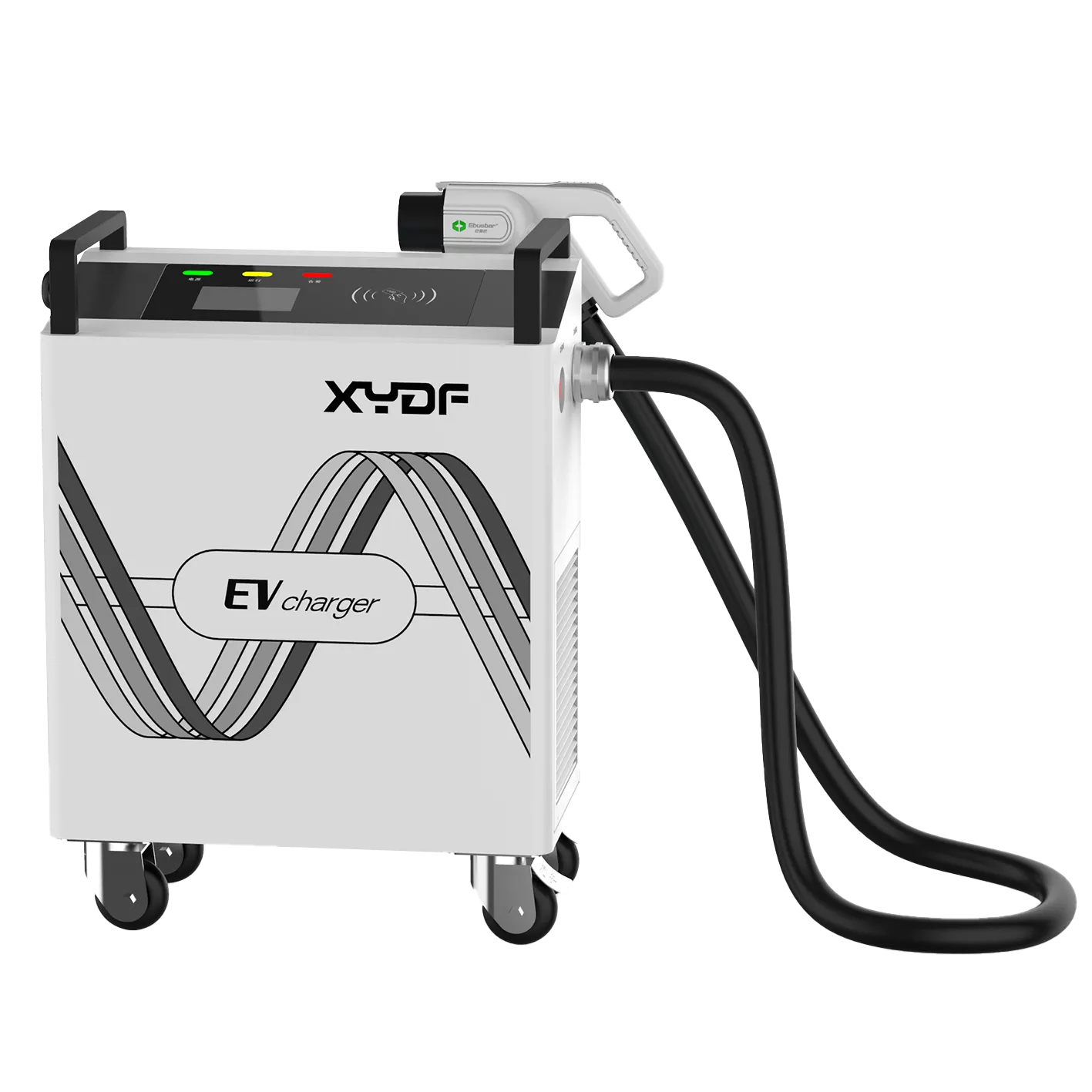
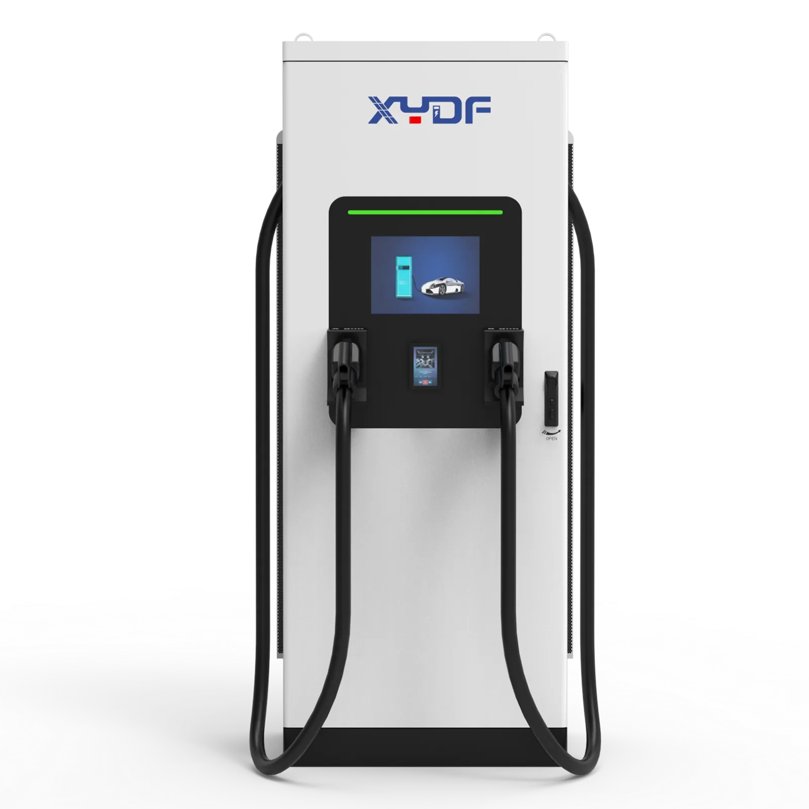
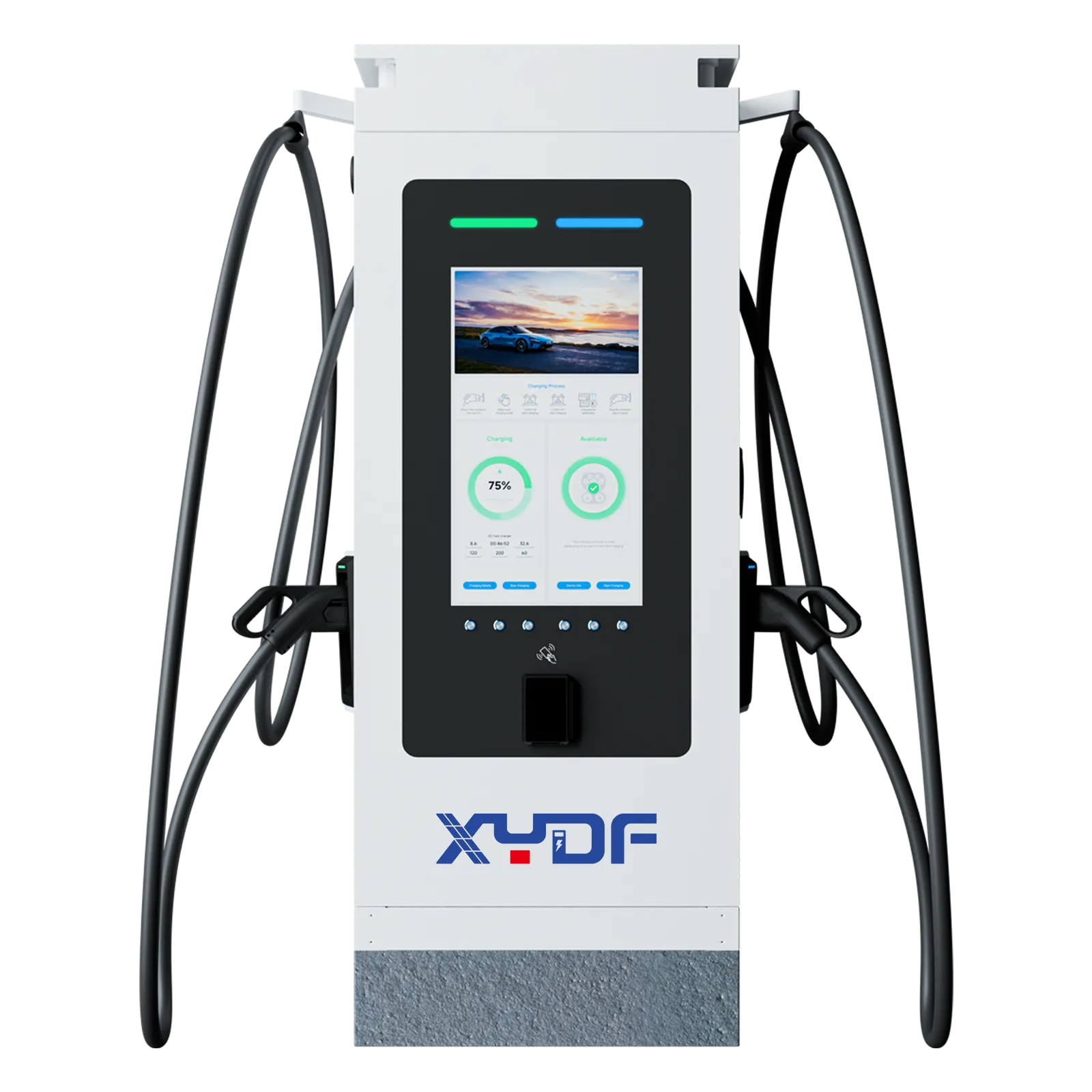
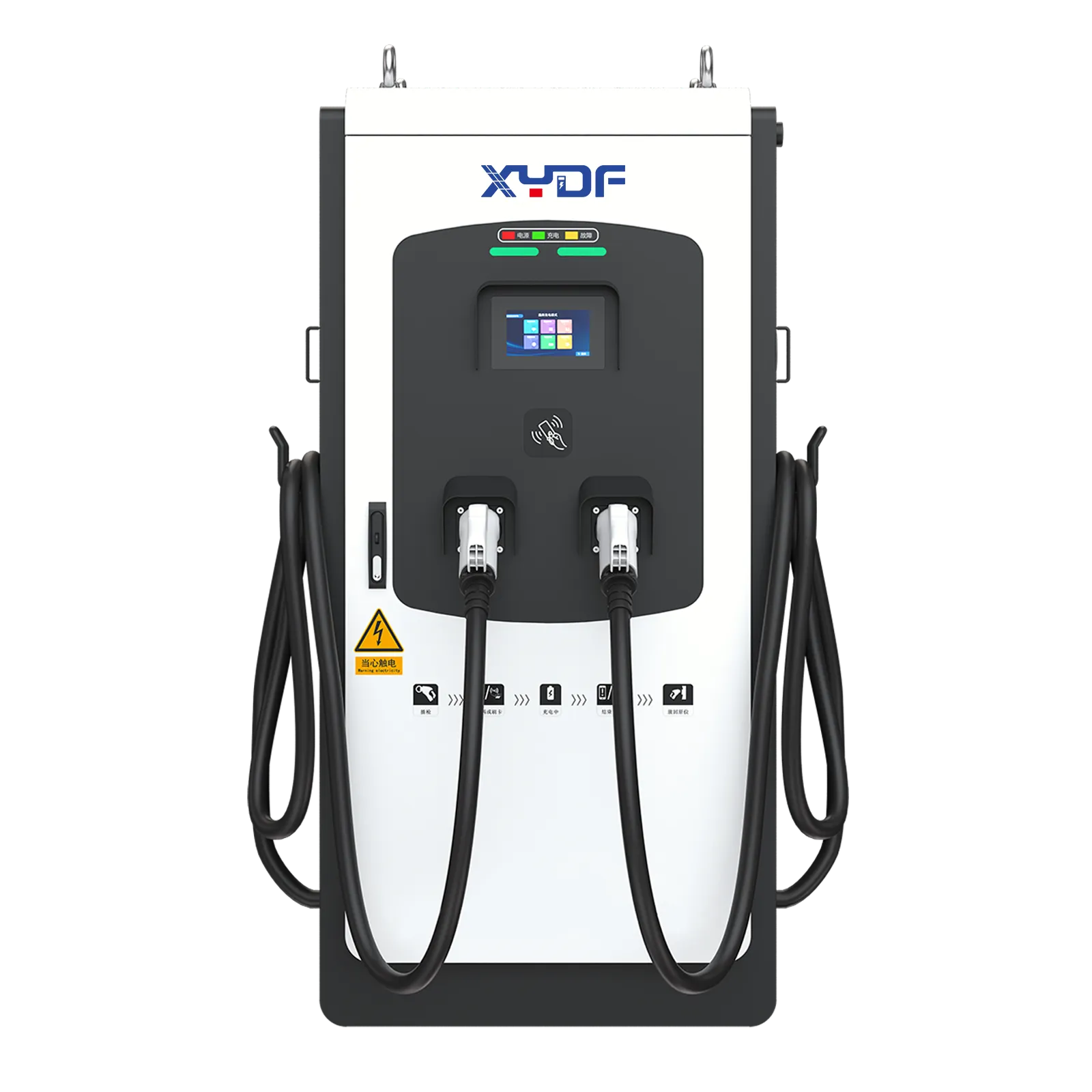
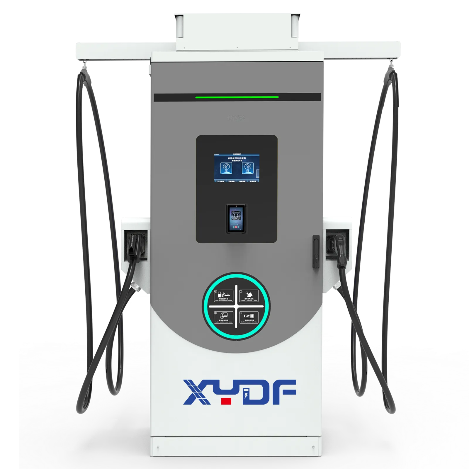
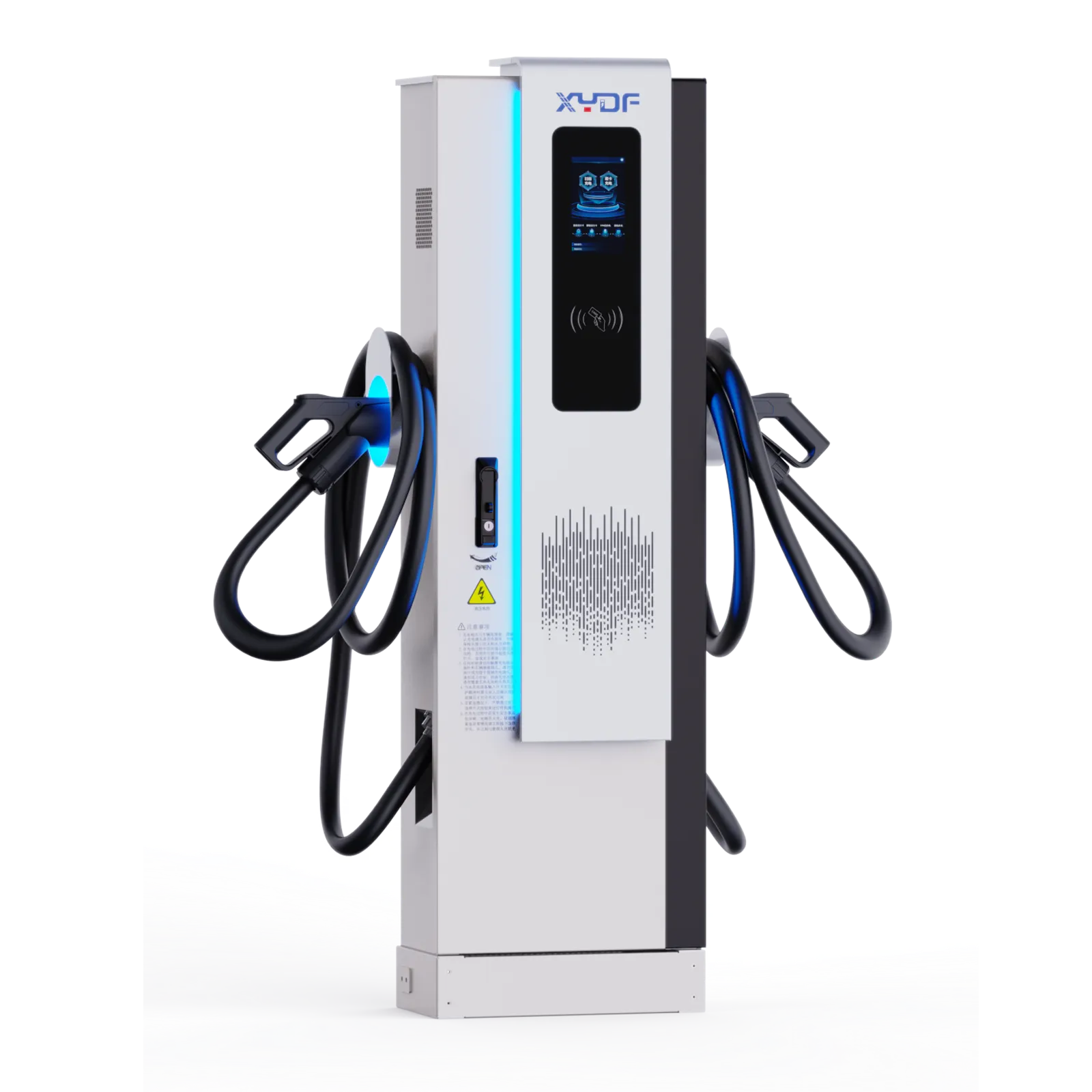
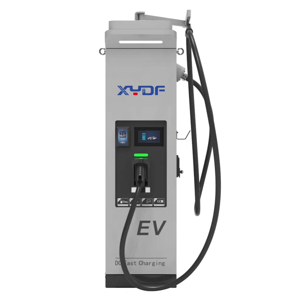
Summary: Liquid-cooled DC fast chargers require a maintenance baseline and escalation triggers covering coolant condition, pump operation, filters, fans, heat exchangers, connectors, insulation systems, firmware, OCPP monitoring, safety devices, and service records. The manufacturer’s current manual and safety procedure control the work; monthly and quarterly tasks in this article are planning baselines, not universal requirements. Preventive rounds should be shortened when utilization, ambient heat, road dust, salt, moisture, connector abuse, or alarm trends increase. IEC 61851-23:2023 defines requirements for DC EV supply equipment and includes energy transfer with a thermal-management system, but it does not prescribe a site’s maintenance interval.
For high-power EV DC fast charging sites, maintenance is not only a service task; it protects uptime, cable temperature control, user experience, warranty position, and charging-station ROI. Public charging infrastructure continues to expand as EV adoption rises, as documented in the International Energy Agency’s Perspectives mondiales des véhicules électriques 2026. Deployment volume alone does not guarantee reliable service. For CPOs and fleet operators, a poorly maintained EV DC charger can create lost sessions, driver complaints, SLA penalties, and higher lifetime cost.
Liquid-cooled charging is becoming more important as public networks move beyond 50–120 kW units toward 300 kW, 360 kW, and 480 kW-plus high-power systems. As 400 V and 800 V EV platforms scale across Europe, fleet depots, motorway hubs, and commercial sites need faster turnover without overheating connectors and cables. Power rating alone does not set a maintenance interval: the decisive factors are the OEM instructions, delivered energy, session count, connector insertions, sustained high-current time, environment, and fault history.
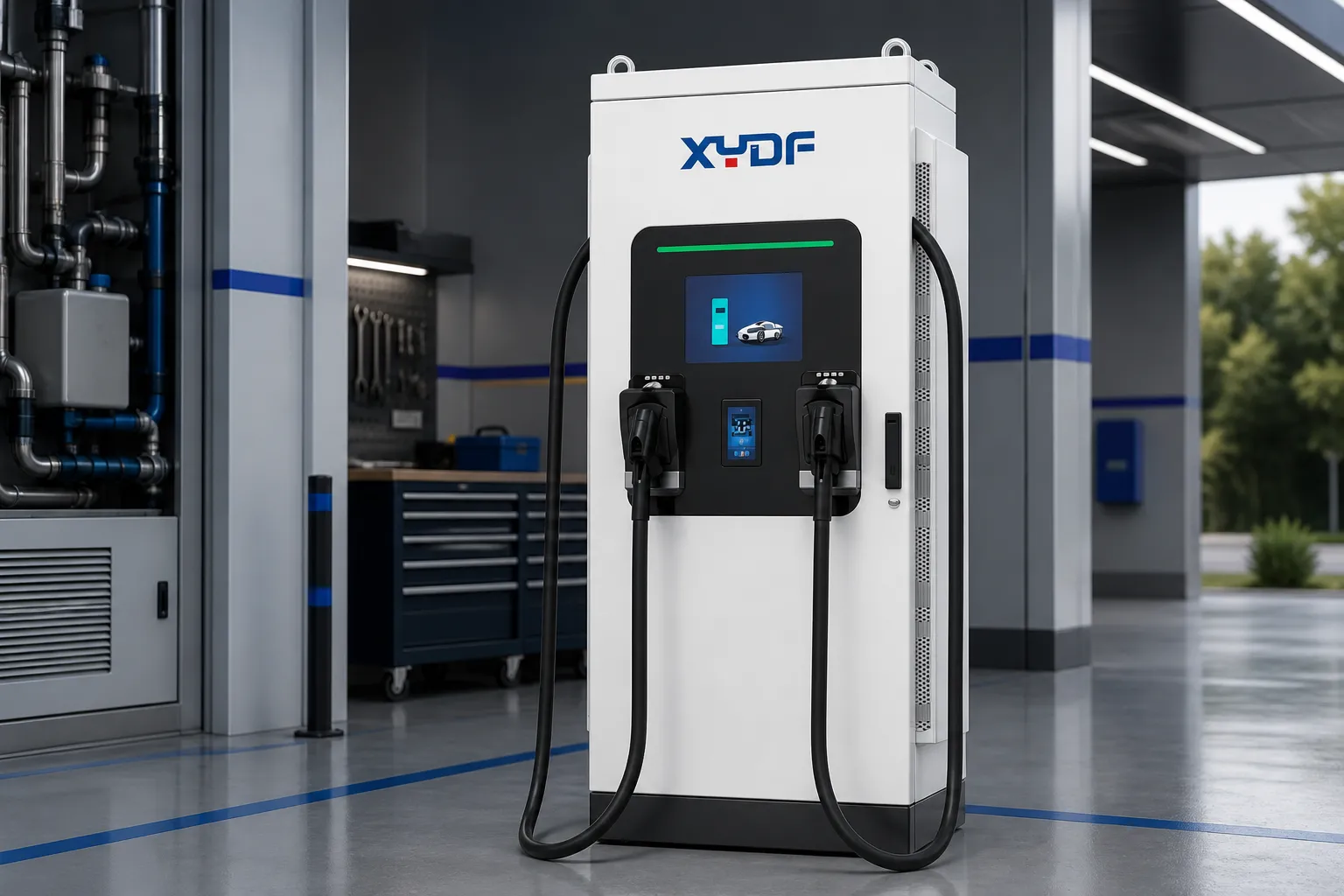
What Happens Inside the Coolant Loop?
The coolant loop is the heart of a liquid-cooled high-power charger. In a 300–360 kW system, the charging cable and internal thermal path may need to manage high current while keeping connector and cable temperatures within safe operating limits. IEC 61851-23:2023 addresses DC EV supply equipment, while IEC TS 62196-3-1:2020 applies to DC connector, inlet, and cable assemblies intended for thermal management at rated currents up to 500 A and voltages up to 1,500 V DC. These standards define equipment and conformity-test scope; the charger and cable manufacturers define approved fluid, fill level, pressure limits, inspection method, and replacement procedure.
A practical external inspection should collect a repeatable coolant-loop evidence set before anyone opens the circuit. Record reservoir level against the marked range at a comparable temperature state; look for stains, wet fittings, hose swelling, abrasion, or crystallized residue; review low-flow, pump, pressure, and temperature alarms; and, where the charger exposes them, capture pump current, flow or pressure, coolant inlet and outlet temperatures, ambient temperature, delivered power, and connector temperature. A single temperature reading without load and ambient context is weak evidence. A repeated temperature rise, pressure loss, level change, or alarm under comparable operating conditions is much more useful.
A practical coolant-loop inspection should include:
- Coolant level: check the reservoir against the marked operating range.
- Coolant quality: look for discoloration, contamination, particles, or abnormal odor.
- Coolant concentration: verify freeze and corrosion protection where climate requires it.
- Pump operation: confirm stable circulation, noise level, and pressure behavior.
- Hoses and seals: inspect for sweating, cracking, looseness, or leakage.
- Liquid-cooled cable path: check for bending damage, abrasion, or flow alarms.
- Alarm history: review temperature and flow-related error codes.
Where should the inspection boundary be?
Operator rounds should normally stop at non-invasive checks: visible reservoir level, accessible leak indicators, cabinet and cable condition, alarm history, and remote telemetry. Sampling, draining, refilling, bleeding, opening fittings, pressure testing, or replacing a pump belongs to technicians authorized by the charger and cable service procedure. Before internal work, isolate all energy sources, apply the site’s lockout/tagout process, verify absence of voltage, wait for stored energy to discharge as the manual specifies, allow hot components to cool, and relieve pressure only through the OEM procedure. Do not mix coolant types or add a fluid simply because its color looks similar.
An active leak, coolant near energized parts, rapid reservoir or pressure loss, repeated low-flow or overtemperature alarms, a hot or visibly damaged connector, or a cable with compromised jacket or strain relief is an isolation and escalation condition. Take the affected port out of service and follow the manufacturer’s release-to-service test. If coolant level drops below the recommended range, the charger may not fail immediately; it may derate. That partial failure is commercially dangerous because drivers see a working screen but receive a slower session. For any DC charger EV project above 300 kW, coolant evidence belongs in the operator’s monthly performance review, not merely an annual service visit.
Why Do Filters, Fans, and Heat Exchangers Still Matter in Liquid-Cooled Chargers?
Liquid-cooled chargers still need air-side heat rejection. The coolant moves heat away from cables and internal components, but fans, radiators, air inlets, filters, and heat exchangers must remove that heat from the cabinet. At a motorway site in 40°C summer conditions, blocked airflow can cause thermal stress even when the coolant circuit itself is intact.
IEC 61851 provides the general charging-system framework, while environmental suitability also depends on enclosure design, declared IP rating, pollution, corrosion exposure, and regional installation practice. An IP rating is not a maintenance exemption. Outdoor equipment can remain protected against defined ingress conditions and still lose heat-rejection capacity when intake surfaces are loaded with dust or debris.
Common site conditions that increase maintenance demand include:
- Road dust and brake particles near highways
- Leaves and insects around rural or suburban sites
- Salt mist near coastal areas and ports
- Industrial particles near factories or logistics yards
- High summer temperatures in open asphalt car parks
- Snow, ice, standing water, or blocked drainage in cold and wet climates
- Frequent high-power sessions that leave little cool-down time
For a 360 kW liquid-cooled charger, quarterly filter cleaning may be a reasonable planning baseline at a clean urban site, while a dusty logistics yard may need monthly inspection or an interval triggered by filter pressure, fan command, cabinet temperature, or recurring derating. The OEM manual takes precedence. A clogged filter increases fan load, reduces heat-exchanger performance, raises cabinet temperature, and can force power derating. The business chain is straightforward: lower thermal headroom reduces charging speed; slower charging reduces session throughput; lower throughput weakens the ROI of DC EV charging stations.
How Do Connectors, Cables, and Sensors Affect Charging Speed?
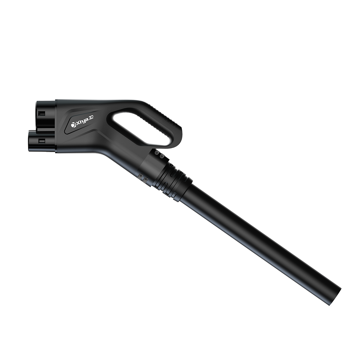
Connectors are where electrical performance, user behavior, and thermal management meet. CCS2 is common across much of Europe, CCS1 remains deployed in North America, CHAdeMO remains in some legacy networks, and GB/T is used in China. IEC 62196 defines plugs, socket-outlets, vehicle connectors, and inlets; SAE J1772 and GB/T 20234 are relevant in their respective markets. Connector selection, inspection limits, and replacement parts must match the destination market and the exact charger configuration.
In high-power operation, a liquid-cooled cable may support current around 500 A depending on its rating, vehicle request, charger architecture, thermal-management state, and ambient conditions. IEC TS 62196-3-1:2020 covers thermal sensing, or thermal transport combined with thermal sensing, for the assemblies within its scope. For 400 V vehicles, current demand can be high at a given power level; for 800 V vehicles, the same power can be delivered at lower current. That is why 400 V / 800 V compatibility is not only a sales feature; the actual current and duty cycle change cable and contact heating.
Connector and cable maintenance should include:
- Inspect CCS pins for discoloration, pitting, or deformation.
- Check locking mechanism and plug seating.
- Confirm temperature sensor readings against abnormal derating events.
- Inspect cable jacket for cuts, crush damage, and twisting.
- Confirm cable retractor or holder prevents ground abrasion.
- Check bend radius and strain relief.
- Review failed session logs for connector-related patterns.
Connector and cable derating should be treated as a protective response, not a fault to override. A worn or contaminated contact can increase resistance and local heating; a failed or biased temperature sensor can cause false derating or conceal a developing problem. Repeated temperature imbalance between connectors, derating at lower loads than comparable ports, visible pin damage, lock failure, coolant or flow alarms, or a compromised cable jacket should trigger removal from service and qualified inspection. Do not return the port to full current merely because a remote reset clears the alarm.
Not every slow session proves a charger defect. The vehicle can request less power because of battery temperature, state of charge, or its own charging curve. Distinguish charger-side derating by comparing requested and delivered current, charger thermal alarms, connector temperatures, ambient conditions, and behavior across vehicles. For a busy DC electric charging station, that comparison prevents unnecessary parts replacement while catching repeated thermal faults early.
Which Electrical Components Should Be Checked Before They Fail?
Power modules convert AC input into controlled DC output. Many systems use modular 30 kW or 40 kW blocks, allowing service teams to isolate module-level issues while maintaining partial capacity. In high-power architectures, DC output may reach 1,000 V or higher depending on system design and vehicle compatibility.
IEC 61851-23, UL 2202, IEC 60364, and NFPA 70 / NEC may be relevant depending on market and project scope. They are not interchangeable maintenance certificates. IEC 61851-23 applies to DC EV supply equipment; UL 2202 is a North American safety standard for DC charging equipment; IEC 60364 and NFPA 70 address electrical installations in their applicable jurisdictions. Maintenance must follow the approved equipment instructions, local electrical rules, site risk assessment, and employer safety program.
Key checks include:
- Power module dust accumulation and fan condition
- DC bus connections and discoloration
- Contactors and switching behavior
- Insulation monitoring records
- Surge protection device status
- Residual current monitoring or RCD-related protection
- Emergency stop function
- Grounding and earthing continuity
- Terminal torque inspection according to service procedure
- Thermal camera inspection under load
The hidden cost is not only component replacement. Poor cabinet maintenance can create nuisance faults, failed inspections, warranty disputes, or safety incidents. In B2B procurement, ask whether the manufacturer provides service documentation, isolation steps, fault-code interpretation, approved coolant and parts, training boundaries, remote diagnostic fields, and spare-part planning for the expected operating life.
How Can Software and OCPP Data Prevent Unplanned Downtime?
Modern charging stations are software-connected assets. OCPP 1.6 remains widely used. OCPP 2.0.1, released in 2020, added device management, monitoring, improved transaction handling, security, smart-charging functions, and ISO 15118 support; its edition 3 was approved as IEC 63584 in 2024. OCPP 2.1 was released in 2025 and adds functions including ISO 15118-20 and bidirectional charging support. The Open Charge Alliance notes that OCPP 1.6 and 2.0.1 are not compatible, so an upgrade is a system-integration decision rather than a routine firmware patch.
OCPP can expose status and diagnostic evidence, but it does not define a universal coolant-change or inspection interval. ISO 15118 supports vehicle-to-charger communication, including Plug & Charge in compatible ecosystems. Operators should map protocol events and vendor fault codes to physical inspection steps, then validate remote findings at the equipment when safety or repeated derating is involved.
For operators targeting 97–99% uptime, software maintenance matters as much as mechanical cleaning. In the United States, the current 23 CFR 680.116 rule requires each charging port covered by the NEVI program to maintain greater than 97% average annual uptime and defines how that uptime is calculated; this is not a worldwide requirement for every charger. A charger with good coolant and clean filters can still lose revenue if backend communication, payment processing, firmware, or session authorization fails.
Recommended software and data checks include:
- Monthly review of charging session logs
- Error-code trend analysis
- Firmware version control
- OCPP connectivity health
- Payment terminal and network testing
- SIM card, Ethernet, or router inspection
- Load balancing settings
- ISO 15118 compatibility review where required
- Remote reset and diagnostic function testing
- Cybersecurity patch planning
A maintenance team should distinguish one-off driver behavior from repeated system patterns. If derating appears at the same ambient temperature, on the same connector, or at the same time of day, the data may point to a thermal or load-management issue. If failed sessions cluster around payment authorization, the cause may be backend communication rather than hardware. For operators of commercial DC electric car charging station products, remote diagnostics can reduce unnecessary truck rolls and improve response time, but only when logs are retained, reviewed, and tied to work orders.
What Should Be Included in a Liquid-Cooled DC Fast Charger Maintenance Checklist?
Use the following as a planning matrix. Replace every baseline with the applicable OEM interval if it is shorter or more specific, and shorten it when condition evidence warrants. Calendar inspection alone is not enough for a high-use site: also track delivered energy, session count, connector operations where available, sustained high-current time, alarms, and environmental exposure.
| Maintenance Area | Que vérifier | Suggested Frequency | If Ignored | Business Impact |
|---|---|---|---|---|
| Coolant level and quality | Reservoir level, color, contamination, concentration | Monthly / quarterly | Thermal derating, corrosion, pump stress | Slower sessions, reduced uptime |
| Pump and coolant circulation | Pump noise, flow alarm, pressure behavior | Quarterly | Poor circulation, cable overheating | Emergency service visit |
| Filters and air inlets | Dust, leaves, insects, blocked vents | Monthly / quarterly | Reduced airflow | Lower charging power |
| Heat exchanger / radiator | Dirt, corrosion, fan airflow | Quarterly | Heat rejection failure | Peak-hour derating |
| Liquid-cooled cable | Jacket damage, bend radius, flow integrity | Monthly | Cable overheating or leakage | High replacement cost |
| CCS connector pins | Wear, pitting, discoloration, locking | Monthly | High resistance and heat | Failed or slow sessions |
| Capteurs de température | Abnormal readings, repeated alarms | Quarterly | False or missed derating | Safety and reliability risk |
| Modules d'alimentation | Dust, fan status, module fault logs | Quarterly / annually | Module failure or reduced output | Capacity loss |
| Surge protection | SPD indicator and protection status | Quarterly / after storm | Damage from transient voltage | Expensive repairs |
| Grounding and insulation | Continuity, insulation monitoring records | Annually / after fault | Safety risk, inspection failure | Liability exposure |
| Firmware / OCPP logs | Versions, errors, connectivity, resets | Monthly | Backend failures, poor diagnostics | Lost transactions |
| Payment and network connection | POS, router, SIM, Ethernet | Monthly | Failed authorization | Revenue loss |
| Emergency stop and signage | E-stop function, labels, user instructions | Monthly | Unsafe response or compliance issue | Inspection and safety risk |
This checklist should be adapted to the charger manufacturer’s manual, local electrical rules, and site utilization. A low-use charger in a sheltered car park will not need the same schedule as a 480 kW highway hub running continuous EV DC fast charging sessions.
How should preventive and condition-based work be combined?
Preventive maintenance creates the minimum opportunity to inspect known wear and safety points. Condition-based work brings a task forward when evidence changes: rising fan command for the same load, repeated connector-temperature imbalance, falling coolant level, abnormal pressure or pump current, increasing failed sessions, corrosion, a storm, impact, vandalism, or a firmware change. A condition trigger can shorten an interval; it should not be used to extend a mandatory OEM or regulatory interval without written engineering approval.
How Should Maintenance Priorities Change by Power Level and Site Type?
| Site Type | Puissance typique | Cooling Risk | Maintenance Priority | Buyer Note |
|---|---|---|---|---|
| City charging site | 60–120 kW | Modéré | Connector, payment, cabinet cleaning | Liquid cooling may not always be required |
| Dépôt de flotte | 150–240 kW | Medium to high | Load management, scheduled uptime, cables | Nightly charging windows make downtime costly |
| Motorway charging site | 300–360 kW | Haut | Coolant, filters, heat exchanger, OCPP logs | Peak-hour reliability drives ROI |
| Ultra-fast hub | 480 kW+ | Very high | Thermal system, grid interface, spare parts | Preventive maintenance must be formalized |
| Port / logistics yard | 150–360 kW | Corrosion and dust risk | Salt mist, filters, grounding, connectors | Inspect more often in harsh environments |
| Hot climate site | 180–480 kW | High ambient temperature | Airflow, coolant, derating logs | Design shading and ventilation early |
| Cold climate site | 120–360 kW | Freeze protection risk | Coolant concentration, cabinet heating | Confirm low-temperature operation limits |
The pattern is clear: as power rises, thermal management becomes a core operating discipline. For high-utilization Bornes de recharge pour véhicules électriques DC, the maintenance plan should be designed before installation, not after the first fault report.
Interval design should also use duty and environment. A lightly used 360 kW charger may accumulate less connector wear than a continuously used 150 kW unit; a coastal or dusty site may need shorter visual and cleaning intervals regardless of nameplate power.
Which Standards and Compliance Requirements Affect Charger Maintenance?
Maintenance supports safety, inspection readiness, warranty claims, and backend interoperability, but a standard’s scope must not be overstated. A product standard or technical specification does not replace the OEM service manual, and a protocol version does not certify the complete charging station.
Depending on target market and project scope, buyers and operators may need to consider:
- IEC 61851-1: general conductive charging system requirements
- IEC 61851-23: DC charging station requirements
- IEC 61851-24: digital communication between DC charger and EV
- IEC 62196: plugs, socket-outlets, vehicle connectors, and inlets
- ISO 15118: vehicle-to-grid communication and Plug & Charge functions
- OCPP 1.6J / OCPP 2.0.1: charger-to-backend communication
- UL 2202: DC charging equipment safety requirements
- UL 2594: electric vehicle supply equipment requirements
- SAE J1772: North American conductive charging interface context
- GB/T 20234: Chinese charging connector standard
- CE / CCC: market access and conformity requirements depending on region
The current edition detail matters: IEC 61851-23:2023 is the second edition and includes energy transfer with a thermal management system, while IEC TS 62196-3-1:2020 covers thermally managed DC connector, inlet, and cable assemblies within its stated ratings. OCPP 2.1 was released in 2025, but implementation and certification remain version-specific. These updates add scope context; they do not replace the original standards checklist or the equipment manufacturer’s maintenance instructions.
Insufficient maintenance records may create commercial consequences:
- Failed site inspection
- Insurance dispute after an incident
- Warranty rejection due to neglected service
- CPO uptime penalty
- Fleet charging delay
- Backend incompatibility
- Safety-incident investigation
- Lower asset ROI
A defensible service record should identify the site, asset and port; date and technician; reason for work; OEM procedure and revision used; before-and-after condition; ambient and load context for readings; alarms and diagnostic codes; firmware and configuration version; approved coolant or replacement-part identity where relevant; isolation and test steps; photographs when useful; deferred defects; and the person who authorized return to service. For covered U.S. NEVI stations, outage and excluded-time evidence also matters because 23 CFR 680.116 defines the uptime calculation and exclusions. Good records are part of the asset, not administrative decoration.
How Can Buyers Avoid Maintenance Problems Before Installation?
Confirm power level before choosing liquid cooling
Liquid cooling is most valuable where current, utilization, and cable thermal load justify it. A 60 kW urban charger may not need the same cooling architecture as a 360 kW highway unit. Match charger power to vehicle mix, dwell time, site traffic, expected simultaneous demand, and grid capacity.
Design maintenance access before installation
A charger installed too close to walls, landscaping, barriers, or traffic lanes becomes harder to service. Leave practical access for filters, cabinets, coolant reservoirs, cables, lifting or replacement routes, and emergency controls. Maintenance space is not wasted space; it protects future uptime.
Match connector type with the target EV fleet
A European motorway site may prioritize CCS2. A mixed import/export project may need CCS1, NACS, CHAdeMO, or GB/T depending on the vehicle population and local rules. Connector choice affects spare parts, cable service, user compatibility, and technician training.
Specify OCPP and remote-monitoring requirements
Define whether the project requires OCPP 1.6, 2.0.1, or 2.1; remote diagnostics; smart charging; dynamic load balancing; and uptime reporting. Confirm compatibility with the selected charging-station management system and document the tested feature set. Software requirements belong in procurement specifications, not after commissioning.
Choose a manufacturer that supports documentation and preventive maintenance
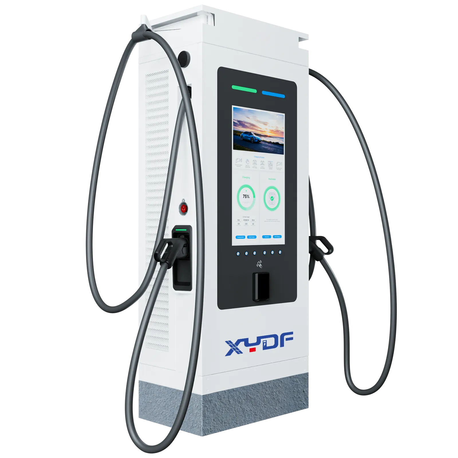
XYDF manufactures DC fast charger systems for commercial and public charging projects, including high-power and liquid-cooled configurations, with documentation support for international B2B buyers. Buyers should confirm the exact model’s service manual, approved coolant, spare-parts list, diagnostic access, training, warranty conditions, and the CE, IEC, UL, CCC, or local conformity evidence required for the target market. Do not assume one configuration or certificate covers another.
FAQ
What is a DC fast charger for EV?
A DC fast charger for EV converts AC grid power into DC power inside the charger, then sends DC power directly to the vehicle battery. Because conversion happens outside the car, charging can be much faster than AC charging. These chargers are commonly used at public charging stations, fleet depots, highway sites, and commercial charging hubs.
Is DC charging good for EV?
Yes, DC charging is useful when drivers need fast charging, especially during long-distance travel or high-utilization fleet operation. Frequent high-power charging can create more battery heat than slow AC charging, so the vehicle’s battery-management system controls charging speed to protect the battery. For daily low-speed charging, AC charging is often enough; for speed and turnover, EV DC fast charging is valuable.
Can you have a DC EV charger at home?
Technically yes, but in most cases it is not practical. A home usually lacks the electrical capacity, installation space, and cost justification for a DC EV charger. Most residential users choose AC home chargers, while DC chargers are mainly used for commercial sites, fleets, parking operators, and public DC EV charging stations.
Which EV supports DC fast charging?
Most modern EVs support DC fast charging, but the connector type, voltage platform, and maximum charging rate vary by model. Many European EVs use CCS2; North American vehicles may use CCS1 or NACS depending on the market; some older models use CHAdeMO; and Chinese-market vehicles may use GB/T. Always confirm the vehicle’s charging standard and maximum DC charging power.
How fast does a DC charger charge?
Charging speed depends on charger power, vehicle battery voltage, battery state of charge, temperature, and the vehicle’s battery-management system. A 60 kW charger may add useful range in under an hour, while a 150–350 kW charger can charge many compatible EVs much faster, often adding significant range in 15–30 minutes. Actual speed is usually highest at low-to-mid state of charge and slows as the battery fills.
When should a liquid-cooled charging port be taken out of service?
Isolate and escalate when there is an active coolant leak, coolant near energized parts, rapid level or pressure loss, repeated low-flow or overtemperature alarms, connector pin damage, unreliable locking, a compromised cable jacket or strain relief, or temperature behavior outside the manufacturer’s limits. A remote reset is not a release-to-service test; follow the OEM procedure and local electrical-safety rules.
Références
- IEC Webstore — IEC 61851 and related EV charging standards
- ISO — ISO 15118 vehicle-to-grid communication
- Open Charge Alliance — OCPP information
- CharIN — CCS and high-power charging ecosystem
- International Energy Agency — Global EV Outlook 2024
- IEC 61851-23:2023 — DC electric vehicle supply equipment
- IEC TS 62196-3-1:2020 — Thermally managed DC connector and cable assemblies
- U.S. Department of Energy AFDC — EV charging infrastructure operation and maintenance
- Electronic Code of Federal Regulations — 23 CFR 680.116 Operations
- Open Charge Alliance — OCPP protocol versions and functions
- International Energy Agency — Global EV Outlook 2026
A liquid-cooled charger does not start losing value only when a component breaks; it starts losing value when heat, airflow, coolant, data, connectors, and inspection records are ignored.
XYDF builds DC fast charging solutions for the point at which charging uptime becomes a business requirement, not just a technical specification. To compare options for public charging, fleets, and commercial projects, review the Catégorie des chargeurs rapides DC et available charging products, then contact the team with the target vehicle mix, site duty cycle, environment, protocol, and service-documentation requirements.