Modular DC Fast Chargers: Capacity Expansion, Repair, and Downtime
Jul 30,2026
Blog
modular DC fast charger architecture spreads power conversion across parallel modules instead of one large converter. That design affects what happens when a component fails, how quickly service can restore capacity, and whether the site can expand without replacing the station. Buyers still need to map shared power blocks, distinguish N+1 from reduced-output operation, verify the expansion path, and accept the actual failure behavior with repeatable tests.
Define modules, power blocks, and shared components
In a modular design, multiple independent power modules work in parallel—commonly in the tens of kilowatts each—and total output is built by stacking them, as the EEPower modular-architecture article describes. The architecture extends beyond the modules: control logic manages the pool, and larger systems may use a shared power unit to allocate module output dynamically across dispensers, as explained in the Tritium architecture overview.
Module architecture is a different decision from station format. Power electronics may live inside each charging post in an all-in-one design or in a central cabinet feeding separate dispensers in a split design. The all-in-one versus split charging guide covers that format choice; modularity describes how conversion inside either format is built.
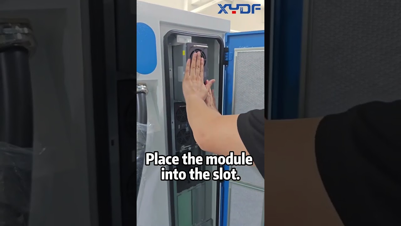
This short video shows the physical installation context for a DC charging power module. Follow the approved service procedure for any live maintenance work.
The practical failure domain may be larger than one module
A module is only the smallest conversion unit. The practical failure domain may be one module, a group of modules behind one contactor, a shared DC bus, a controller, or a cooling circuit. A procurement drawing should show which modules form each power block, what they share, how a block is disconnected, and whether another block can continue serving a connector. Counting modules without mapping shared elements can make a rack appear more redundant than it is.
Specify fault behavior, N+1 capacity, and derating
With parallel modules, one failed unit can take its own capacity offline while the remaining modules keep charging at reduced power; with a single large converter, a comparable conversion fault typically takes the whole charger offline. That behavior must still be confirmed for the specific architecture because shared controls, dispensers, cables, and cooling can remain single points of failure. The BCG/EcoG analysis likewise treats central power units as an uptime tool and a risk to engineer around.
Event
Monolithic converter
Modular rack
Single conversion fault
Station usually offline
Output reduced; sessions continue
Repair unit
Large assembly, often specialist work
Standardized module
Fault visibility
Whole-unit alarms
Per-module health data
Spare strategy
Model-specific major assembly
Pooled standard modules
N+1 capacity is not the same as graceful or thermal derating
N+1 capacity is a contractual state, not a synonym for modular. In an N+1 design, the installed rack can lose one defined unit and still meet the committed output. In a merely modular design, the station remains operational after the loss but delivers less power. Thermal derating is different again: the controller deliberately lowers output when temperature, airflow, grid input, cable temperature, or another monitored limit approaches its threshold. The tender should state required output after one module or power-block loss and the conditions under which thermal derating may begin.
For example, assume six 30 kW modules. Installed conversion capacity is 6 × 30 = 180 kW. After one module is isolated, 5 × 30 = 150 kW remains. If contracted single-fault output is 150 kW, the sixth module provides N+1 capacity; if contracted output is 180 kW, the same event is graceful derating, not N+1 performance. Verify module ratings and single-fault behavior against the selected XYDF configuration.
Vehicle voltage and current can limit usable module-pool power
Nameplate power alone does not determine session power. Because power equals voltage multiplied by current, a charger limited to 300 A could deliver 120 kW at 400 V but 240 kW at 800 V before other limits are considered. The vehicle also requests allowable voltage and current during the DC control exchange. IEC 61851-24:2023 covers digital communication between DC supply equipment and the vehicle for controlling conductive DC power transfer; it does not promise that every vehicle will accept station nameplate power.
For multi-connector systems, the controller must translate vehicle requests into module assignments. Ask whether allocation is fixed, first-come-first-served, equal-share, schedule-based, or priority-based, then test a mixed-voltage pair of vehicles or vehicle emulators. A balanced module count is not necessarily balanced delivered power when vehicles have different voltage, current, temperature, or state-of-charge limits.
Pass six engineering gates before expanding capacity
Phased deployment starts a site below final capacity and adds modules as demand grows, deferring capital while keeping the upgrade path open. The cabinet, cooling, and wiring are sized for the target, while only the slots required for current demand are populated. Yet adding conversion modules increases only one layer of site capacity; growth stops at the weakest element.
Treat expansion as a short engineering-change process that rechecks the electrical path, heat rejection, control licenses, and operating model. Start with the final demand case in DC fast-charging transformer capacity planning, then record headroom at each downstream gate.
Added capacity is invisible, misallocated, or blocked by software configuration
Do not release an expansion order until the documented expansion envelope passes all six gates. If the transformer is reserved for the final build but switchboard, feeder, or cooling was sized only for phase one, empty module slots do not create a safe upgrade path. The change record should name who recalculates protection, who updates the backend, and which tests are repeated after installation.
Make module repair safe, compatible, and measurable
Published engineering examples describe module swaps completed in minutes to under an hour for well-designed racks, compared with monolithic repairs that may wait days for specialists and parts. One module-reliability write-up reports that a highway operator running eight 360 kW stations had 23 individual module failures across 18 months; with modular hot-swap, total customer-facing downtime was under 11 hours. The same Evaisun source says centralized designs can wait “eight hours or more” for a specialized technician with the correct spare.
Maintenance-architecture vendors describe a similar contrast at controller level: a conventional sequence of dispatch, diagnosis, and disassembly “can take 1 to 10 days,” versus an on-site module swap of minutes after remote diagnostics identify the failed part, according to the Injet maintenance analysis. Read any uptime claim using the method in evaluating EV charging equipment reliability.
A fast swap still requires a documented isolation path
The service procedure should identify the disconnecting device, prove absence of hazardous energy where required, prevent backfeed from shared DC buses, protect adjacent live sections, and state whether the entire cabinet, one power block, or one connector must stop. “Hot-swap” must never replace the manufacturer’s safety procedure. IEC 61851-23:2023 specifies requirements for DC EV supply equipment and adds conformity test methods; it is a design-and-test reference, not evidence that an unspecified charger is certified.
Spare compatibility extends beyond rated power
Match the approved part number and revision, AC and DC ranges, connector keying, communication interface, airflow direction or cooling interface, parameter set, and permitted firmware. Keep a matrix showing which module hardware can run with each rack-controller version, whether mixed revisions are allowed, and the validated upgrade and rollback sequence. The EV charger spare-parts guide turns that matrix into stock levels, response roles, and replenishment terms.
Backend visibility must also be specified. The Open Charge Alliance OCPP overview lists device management and station monitoring among OCPP 2.0.1 functions and notes that OCPP 1.6 and 2.0.1 are not compatible. Protocol capability alone does not guarantee per-module telemetry: the charger must expose the relevant component, alarm, and measurement data, and the charging-station management system must ingest and retain it.
Availability needs a written denominator and separate degraded-capacity reporting
For U.S. projects within its scope, 23 CFR 680.116 requires each charging port to exceed 97% average annual uptime. It defines “up” as hardware and software being online and available or in use while successfully dispensing electricity at the required minimum power, and it provides a minutes-based formula and named exclusions. This is a useful example of a measurable definition, not a universal warranty threshold for every country or private site.
A buyer’s schedule should separately report port availability and degraded-capacity reporting: port-available minutes, full-capacity minutes, degraded-capacity minutes, successful session-start rate, remote-diagnosis time, on-site response time, and repair time. Define planned maintenance, utility outages, vehicle-caused failures, communications outages, and force-majeure exclusions before comparing bids. The U.S. Department of Energy’s Alternative Fuels Data Center guidance on charging operations and maintenance likewise recommends that maintenance contracts include response time, repair time, and an overall uptime requirement.
Verify serviceability and acceptance evidence before purchase
“Modular” on a datasheet spans everything from tool-free racks to designs that still require half a day of disassembly. Serviceability is a design property; the same engineering source that praises well-executed racks warns that poor layouts can turn a swap into “a four-hour job.” Ask for the swap procedure as a document, not a sentence. Time, tools, safety steps, shutdown scope, and technician authorization belong in the service manual reviewed before purchase.
Buyer should verify
Why it matters
Module size, count, and failure behavior
Defines how much power survives a fault
Swap procedure: tools, time, authorization, live or shutdown
Acceptance tests should reproduce normal and degraded operation
Record module, controller, dispenser, meter, and firmware identifiers so the tested configuration can be reproduced.
Using a suitable vehicle emulator, load bank, or documented vehicle set, measure voltage, current, and delivered power at low, nominal, and high points within the contracted range. Apply purchaser-approved tolerances rather than a generic pass value.
Inject or simulate one agreed module or power-block fault under the approved procedure. Verify isolation, alarm identity and timestamp, remaining output, session behavior, and absence of fault propagation.
Run simultaneous connectors with different voltage and current requests. Record allocation priority, transition time, delivered power, and what happens when one vehicle stops.
Run the declared thermal-duty case long enough to reach stable temperatures; record when derating begins, which sensor caused it, reduced output, and recovery behavior.
Interrupt and restore network service, then restart the charger. Verify local charging policy, transaction retention, time synchronization, remote status, alarms, and recovery without an unplanned technician visit.
Install an approved spare or expansion module, confirm hardware and firmware compatibility, repeat the relevant electrical checks, and save the as-left configuration.
These tests should produce timestamped records, not a single “pass” line. Trend the same measures after handover using the reliability-evaluation method linked above. Acceptance proves one controlled configuration; availability reporting shows how it performs in service.
Compare XYDF formats with model-specific documentation
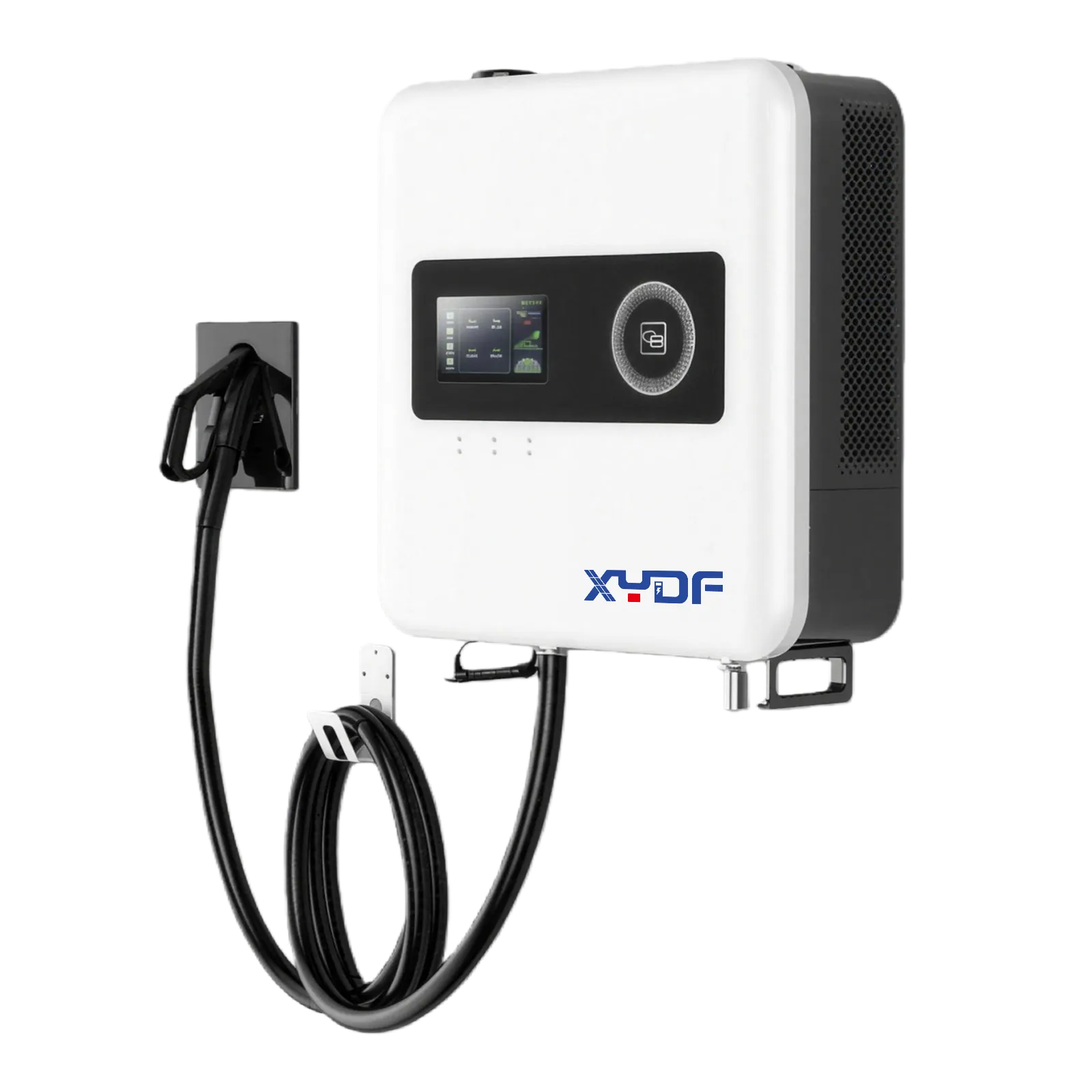
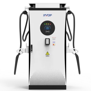
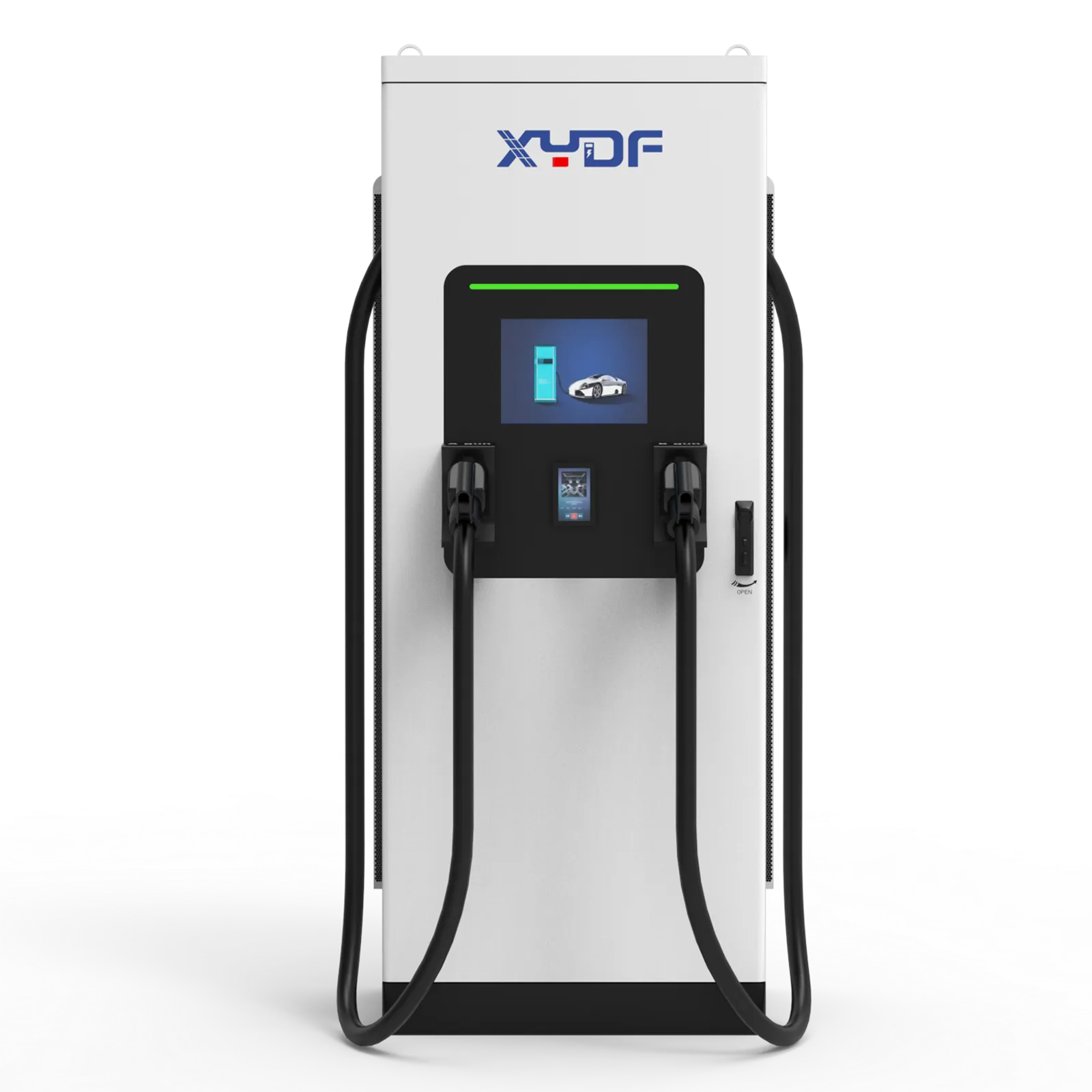
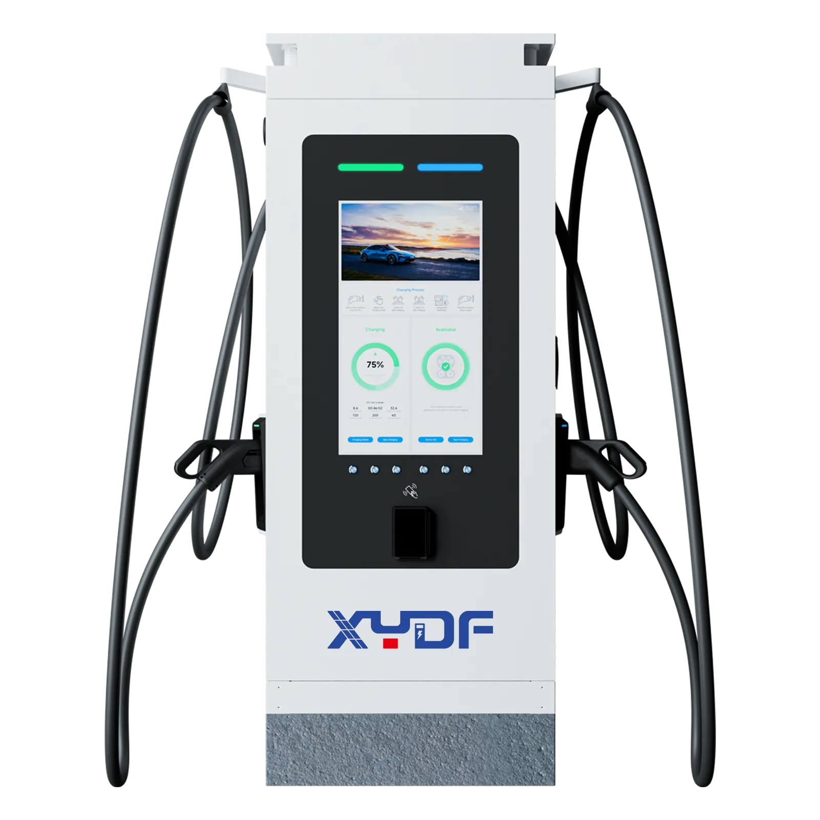
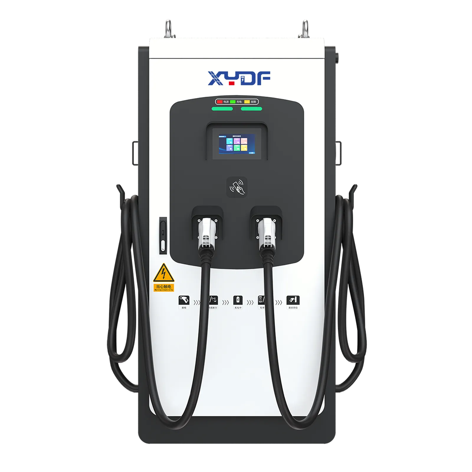
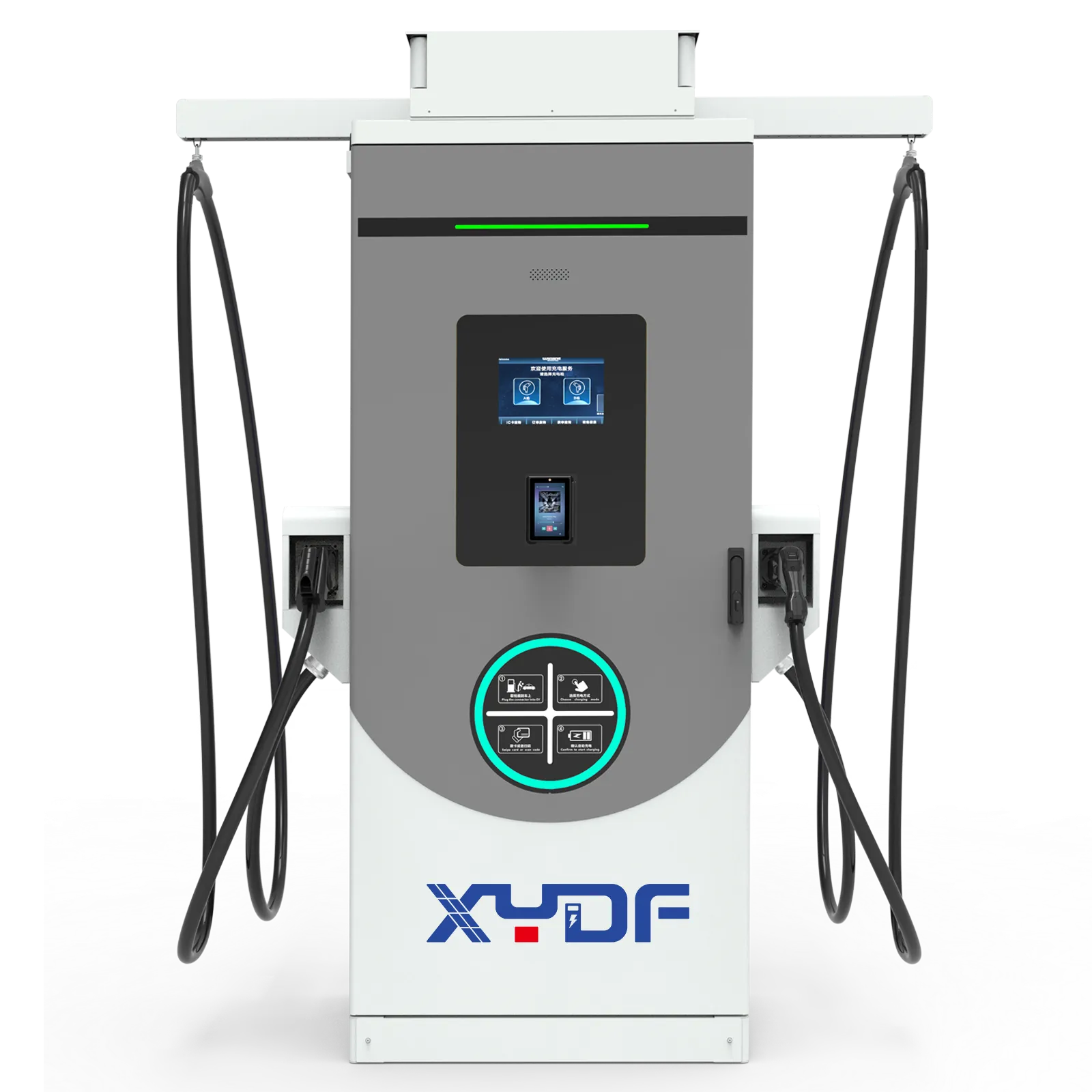
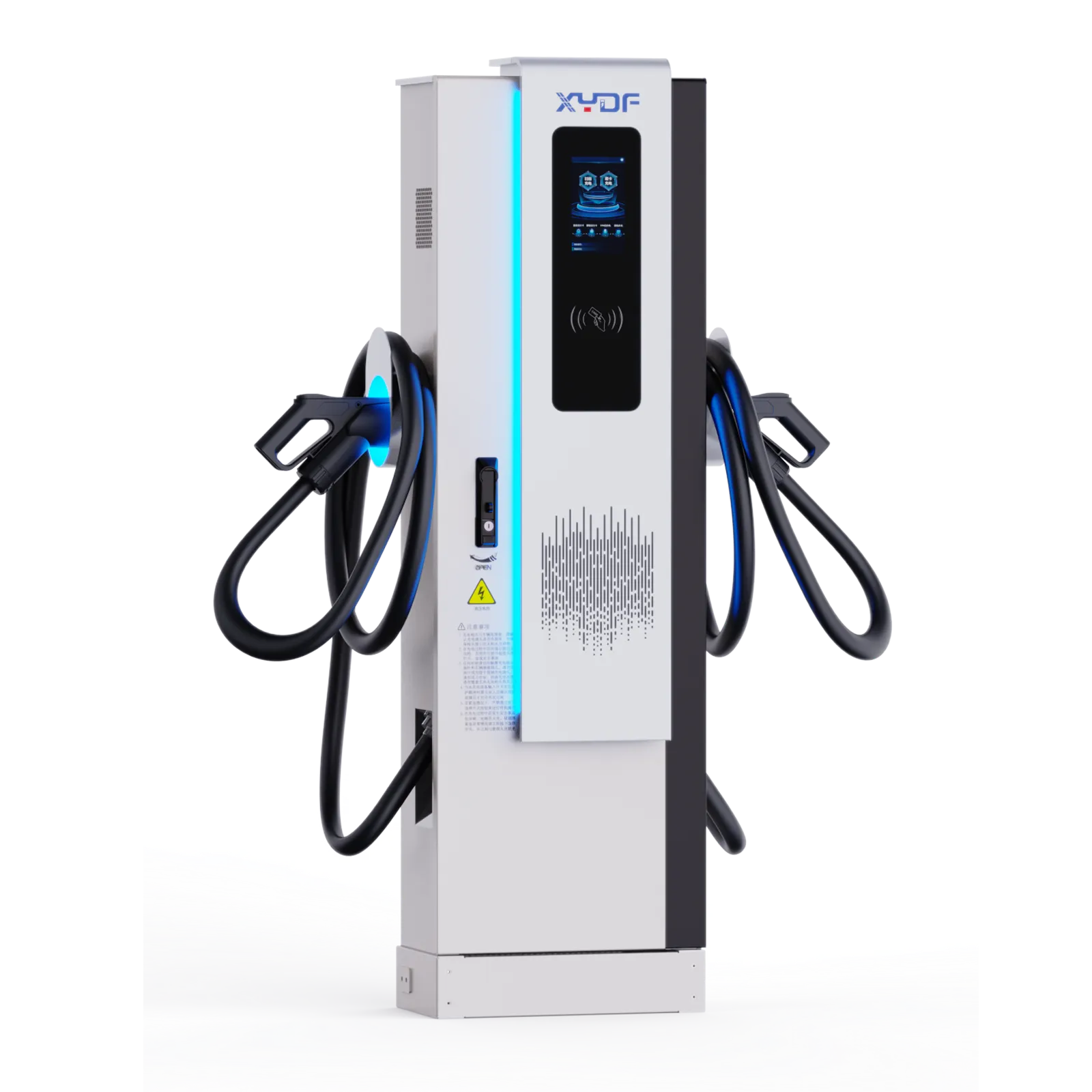
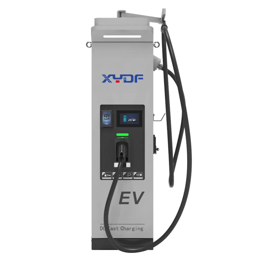
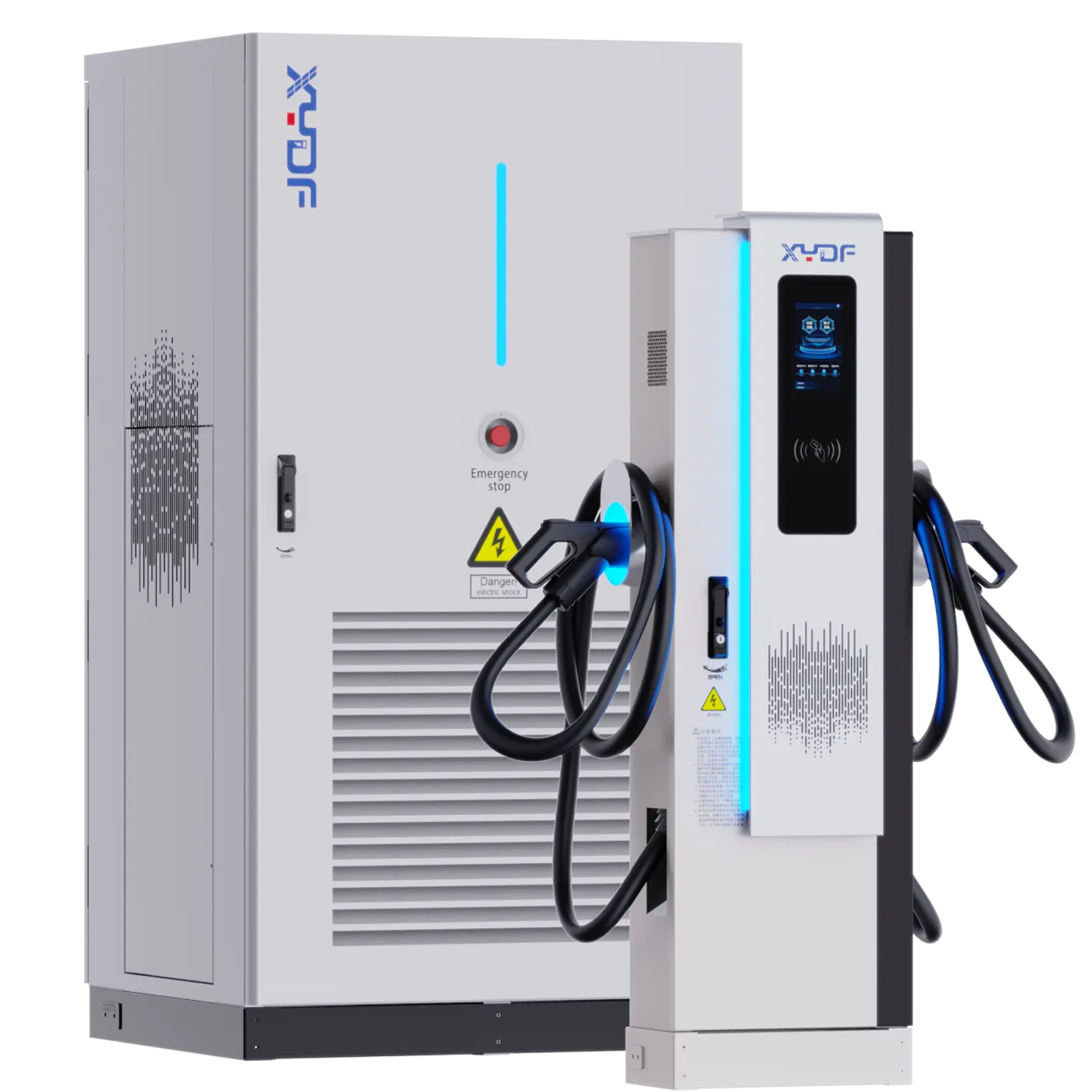
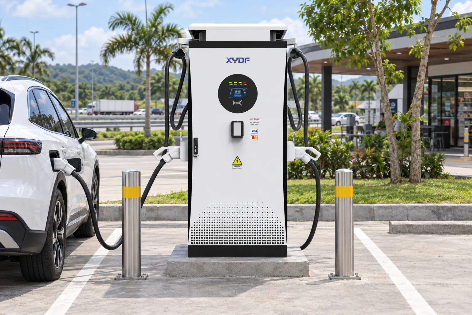
XYDF’s official self-description notes that the company started by manufacturing charging modules, and its DC catalog contains both formats discussed here. For site-scale scalability, the split format—a central power cabinet feeding multiple dispensers—is the natural fit; see the 360kW-720kW split DC fast charging station. Compact single-position sites map to all-in-one cabinets such as the EC Series 80kW-240kW all-in-one charger, with the full DC fast-charger range between.
This guide is for operators and project buyers comparing DC architectures for uptime and growth; it does not state XYDF module sizes, swap times, redundancy behavior, efficiency, pricing, warranty, certifications, uptime, or compatibility. The procurement schedule should name the module and power-block topology, single-fault output, current-versus-voltage envelope, thermal derating logic, six expansion gates, isolation procedure, spare compatibility matrix, firmware policy, telemetry map, acceptance tests, and availability formula.
For a project review, send the intended vehicle voltage range, concurrent charging profile, phase-one and final power targets, ambient design case, backend version, and service metrics through the Xinya EE contact page. Request model-specific drawings, manuals, compatibility lists, module behavior, swap procedure, expansion limits, and test plan before accepting the architecture.
Frequently asked questions
What is a modular DC fast charger?
It is a DC charger whose power conversion is built from multiple independent modules working in parallel, so capacity, failures, and repairs can be handled module by module instead of station by station.
What happens when one power module fails?
The failed module can drop out while the remaining modules deliver reduced power, allowing sessions to continue while repair is scheduled. Confirm the behavior for the specific design, including shared power-block components.
How fast can a power module be replaced?
Published engineering examples describe swaps in minutes to under an hour for well-designed racks, versus days for some monolithic repairs. The defensible answer is the time demonstrated under the model’s documented and safe swap procedure.
Can charger capacity be expanded after installation?
Yes, within the expansion envelope. Free module slots, cooling capacity, switchgear rating, feeders, protection, software configuration, and upstream supply headroom must all support the target rating.
What are the drawbacks of modular chargers?
They introduce more components and connections to manage, require compatibility control across module revisions, and still depend on shared controls, dispensers, buses, or cooling that may be single points of failure.
How does modularity change spare-parts planning?
It can concentrate spares on standardized modules pooled across sites, but only when revision control and per-module diagnostics identify the failed unit before dispatch.
 Xinya Dongfang Electricity Technology Co., Ltd.