 Xinya Dongfang Electricity Technology Co., Ltd.



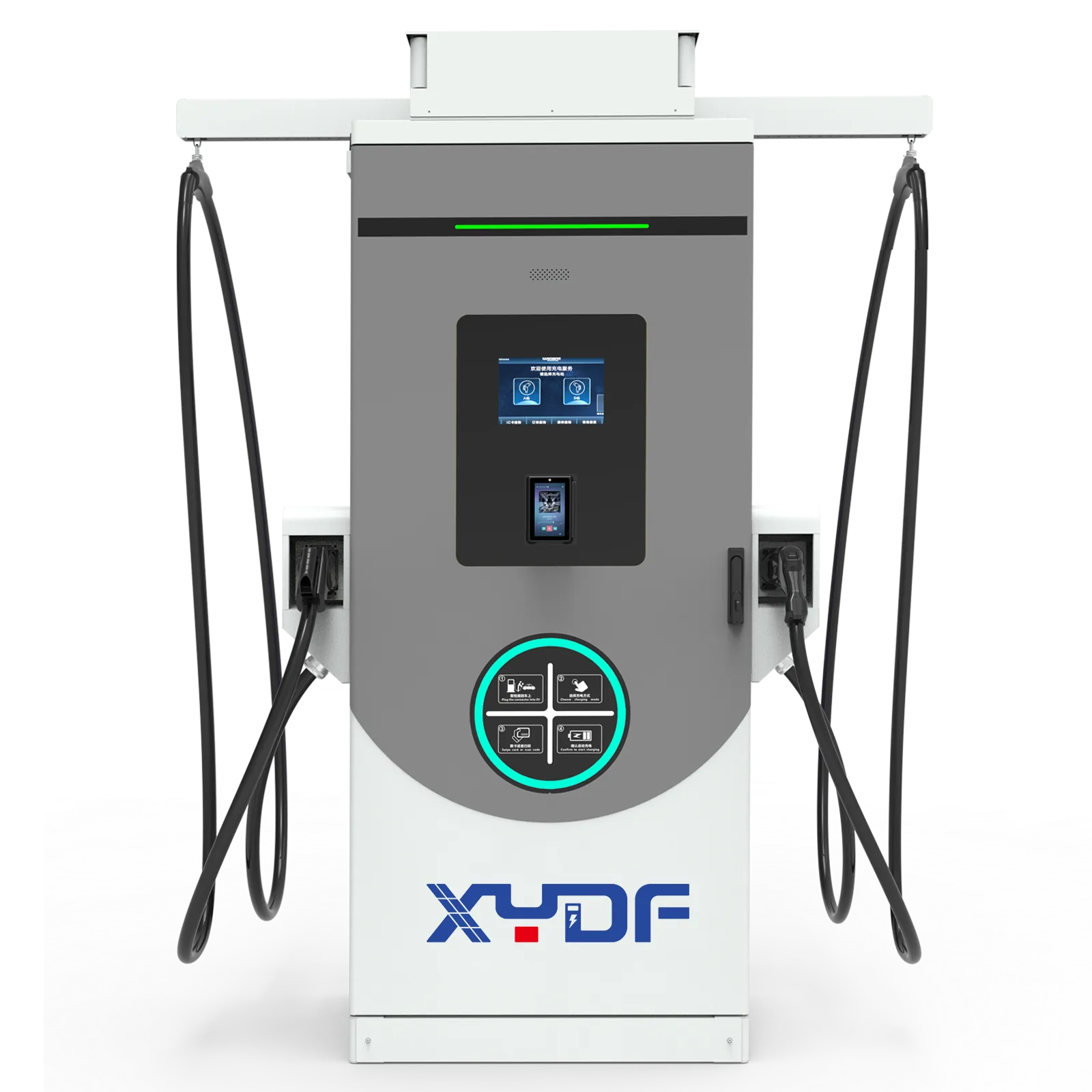
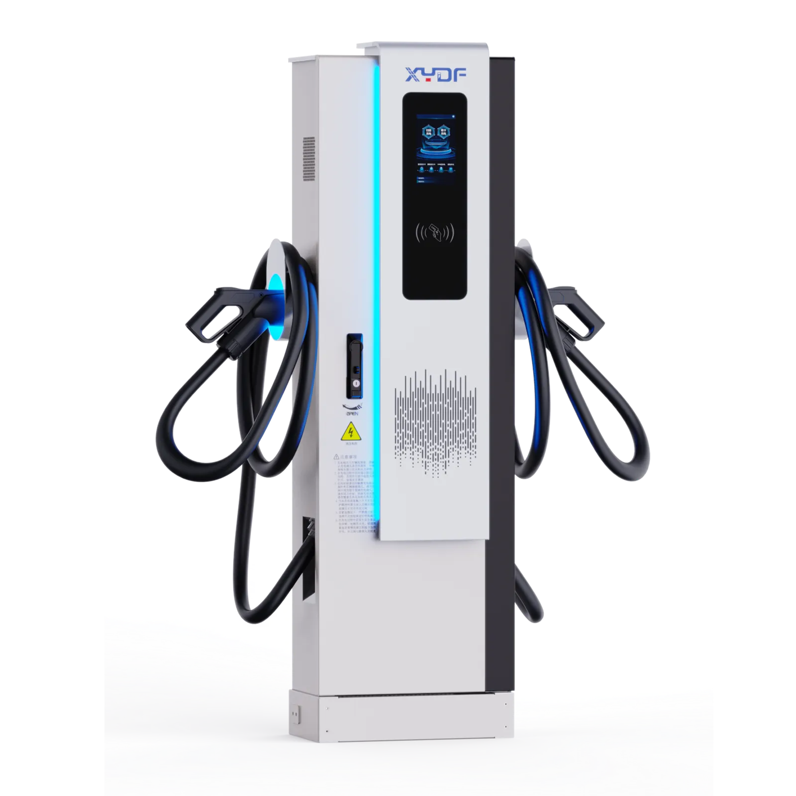
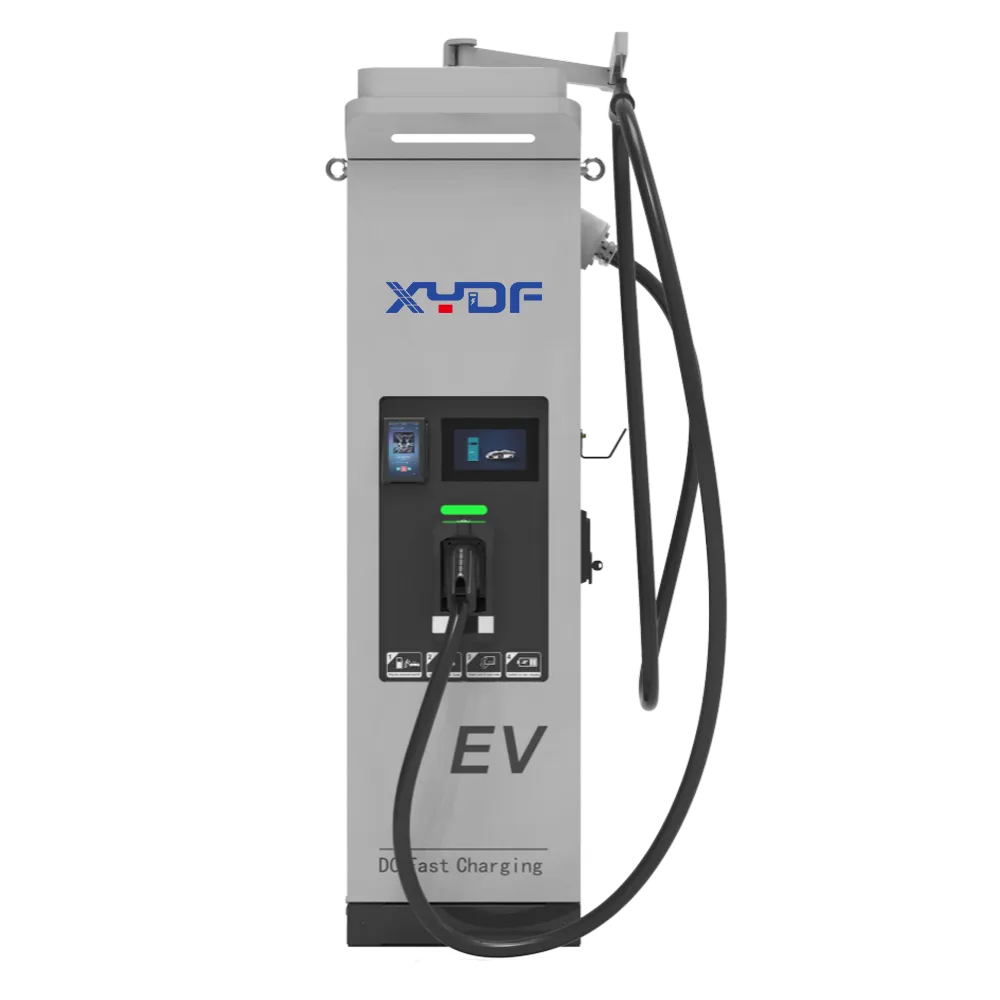

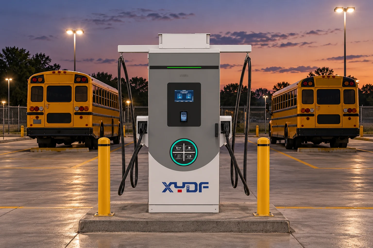
An electric school bus charging depot should be sized around the energy each bus needs before its next departure, the hours it is actually available to charge and the electrical capacity the site can support. Start with routes and operating schedules, then choose chargers and a managed charging strategy. Buying identical high-power units for every parking bay can add cost without solving the routes that have the tightest turnaround.
A useful school bus EV charging plan brings together transportation staff, the utility, the electrical designer, bus suppliers and the charging-system provider. It should cover ordinary school days, cold-weather demand, extracurricular trips, late arrivals and equipment failures. The goal is for every assigned bus to leave with its required reserve, while keeping the yard practical for drivers and maintenance staff.
How do routes and departure times determine charging demand?
Build a route-level worksheet before selecting charger power. Record distance, terrain, stops, passenger loading, weather, cabin heating or cooling, return time and next departure. Use vehicle data from comparable routes where available. Manufacturer range estimates can support an initial screen, but they do not replace a route energy model.
Distinguish battery nameplate capacity from usable capacity and the operating state-of-charge limits agreed with the bus supplier. WRI’s Electric School Bus Initiative highlights this difference and the effect of heating and air conditioning on range. Avoid adding a second reserve for battery capacity already excluded by the manufacturer’s usable-energy figure.
Calculate the energy needed at the next departure, then subtract the energy expected to remain on return. Include a stated operating reserve and any energy needed for preconditioning. Keep the daily case separate from the worst credible route: a long afternoon trip may determine that bus’s charger requirement even when the fleet average is modest.
For school bus route charging, availability is as important as distance. A bus may sit at the depot between morning and afternoon runs, but that window is useful only if it can be plugged in, charged and released in time. Time spent parking, inspection, cleaning and dispatch must be excluded from the effective charging window.
How much charger power does each bus need?
A first estimate is required battery energy divided by the effective charging hours, adjusted for losses. Specify whether the power figure refers to grid input or power delivered to the battery. The actual schedule must also respect the bus’s charging limit, temperature-dependent performance, state-of-charge taper and any power shared with another connector.
Consider an illustrative bus that needs 90 kWh added to its battery before departure. With six effective charging hours and an assumed 90% overall grid-to-battery efficiency, the average grid input is 90 ÷ (6 × 0.90), or about 16.7 kW. If its charging window falls to two hours, the same calculation gives 50 kW. These are planning assumptions, not a measured bus consumption rate or an installation recommendation.
A charger with a matching nameplate rating still needs validation against the vehicle’s accepted power. For AC charging, the onboard charger can be the limit. For DC charging, check the bus voltage range, connector, communication requirements and charging curve. Obtain written compatibility evidence for the actual bus and charger combination.
| Operating pattern | Approach worth evaluating | What must be checked |
|---|---|---|
| Long overnight parking with moderate energy demand | Compatible AC charging or lower-power DC charging | Available hours, onboard AC limit and energy required by departure |
| Short interval between route assignments | A dedicated DC charging window | Bus acceptance curve and actual time at the connector |
| Mixed routes and irregular extracurricular trips | Routine overnight capacity plus a planned recovery option | Which buses need priority and whether spare capacity is accessible |
| Several buses sharing a limited electrical service | Managed power allocation by departure deadline | Feasible energy delivery for every bus under the site limit |
The terms Level 2 and DC fast charging describe different arrangements; they do not establish universal bus compatibility. The Level 2 label is commonly used in North America. Electrical supply, connector standards and vehicle requirements must be checked for the destination market.
How many chargers and connectors should the depot have?
Count simultaneously parked buses, available connections and independently usable power channels separately. Two connectors on one unit may share power or operate sequentially. Ask what each vehicle can receive when both are connected, and what happens to both bays if the shared cabinet fails.
A dedicated connection for each routinely parked bus reduces overnight vehicle moves and makes automated schedules easier to execute. Shared chargers can work when staff are available to move vehicles and the timetable includes those moves. Do not assume that a driver will return late at night to swap cables unless that labor is explicitly planned.
For a hypothetical ten-bus depot with ten simultaneous overnight arrivals, ten accessible connections allow all buses to stay plugged in. That does not require ten chargers drawing full nameplate power at once. The chosen architecture can allocate power across those connections, provided it meets each departure target.
Evaluate a charger outage against the route plan. A spare connector attached to the same failed power cabinet is not independent redundancy. Define which route can use another bay, when a replacement bus is available and who will respond to a missed charging session. This operational reserve is often more useful than specifying an arbitrary percentage of spare equipment.
Can managed charging reduce the utility connection size?
Electric bus depot charging can often spread demand across long parked periods. Managed charging controls when power is delivered and how it is divided. WRI distinguishes this from bidirectional charging: scheduling energy into buses does not require exporting energy from them.
Start with a time-based simulation rather than the sum of charger ratings. For ten buses each needing the illustrative 90 kWh battery addition over six shared hours, at the same assumed 90% efficiency, average grid input is about 166.7 kW. That value is only an energy-over-time estimate. It does not establish transformer size, conductor ratings or a feasible schedule if several buses arrive late or depart early.
Have the designer and utility evaluate the depot’s other loads, available service, demand measurement, transformer loading, protection, power quality and applicable electrical rules. Preconditioning can coincide with morning dispatch and must be represented in the load profile. Compare tariffs using the utility’s actual demand interval and time-of-use periods.
Specify what happens when the cloud connection or central controller is unavailable. The fallback must keep the site within its permitted electrical limit while preserving an agreed operating plan. Test vehicle priority changes and simultaneous restarts after an outage. A system that starts every charger at maximum power after reconnecting can undermine the intended limit.
The charging controls should connect departure priorities with the site cap. The principles of dynamic load balancing help explain power allocation, but the depot must also account for which bus needs to leave first. Storage, solar or V2G can be evaluated separately where the business case and compatibility support them.
What should be agreed with the utility before construction?
Share the first-phase bus count, expected growth, proposed charging windows and a preliminary load profile early. Ask about existing capacity, new service requirements, transformer and switchgear lead times, metering, tariffs and the division of construction responsibilities. A charger delivery date does not establish the date the depot can be energized.
WRI’s Power Planner organizes the utility discussion into practical steps for school districts. Use that early coordination to compare staged expansion with the cost of reopening finished pavement. Civil works may include future conduit routes or equipment space even when the first phase installs fewer chargers.
| Planning input | Who needs it | Decision it supports |
|---|---|---|
| Route energy and departure schedule | Transportation team and charging-system designer | Power, connections and priority rules |
| Existing electrical load and future fleet phases | Utility and electrical designer | Service capacity, equipment and staged upgrades |
| Bus dimensions, inlet position and turning movements | Civil designer and depot operations team | Bay layout, cable reach and circulation |
| Applicable codes and equipment approvals | Designer and authority having jurisdiction | Permits, protection, installation and inspection |
| Failure response and maintenance access | Operator, bus supplier and charger provider | Recovery procedures and service responsibilities |
For US projects, have the qualified designer address the locally adopted electrical code, including applicable EV charging provisions. Other markets use their own electrical, installation and equipment requirements. Product certification, installation approval and successful bus interoperability are different checks; none should be inferred solely from the presence of a connector.
How should buses, cables and people move through the yard?
Map turning paths using the actual bus dimensions and wheelbase. Place chargers where buses can park predictably without driving over cables or striking equipment. Verify connector reach to the real inlet location with the intended parking orientation. Avoid layouts that depend on stretching a cable across a walking route.
Provide appropriate cable storage, equipment protection, lighting, drainage and service access. Plan for snow storage or local weather conditions where relevant. Keep inspection and maintenance work away from ordinary dispatch movements, and preserve emergency access. A neatly drawn parking grid is not sufficient if the first turning bus blocks another bay.
Document who plugs in each bus, confirms the connection and checks readiness before departure. Include missed-plug alerts, loss-of-charge escalation, a safe isolation procedure and coordination with emergency responders. Drivers and maintenance staff need training appropriate to their roles; a general EVSE training course does not replace the bus and charger manufacturers’ instructions.
How should the depot specification be turned into a purchase?
Prepare a short specification covering the route model, vehicle interfaces, usable charging hours, site power cap, weather exposure, control integration and service expectations. Ask suppliers to show how their proposed configuration meets it. Compare installed cost, utility work, network fees, maintenance and dispatch labor, as well as charger price.
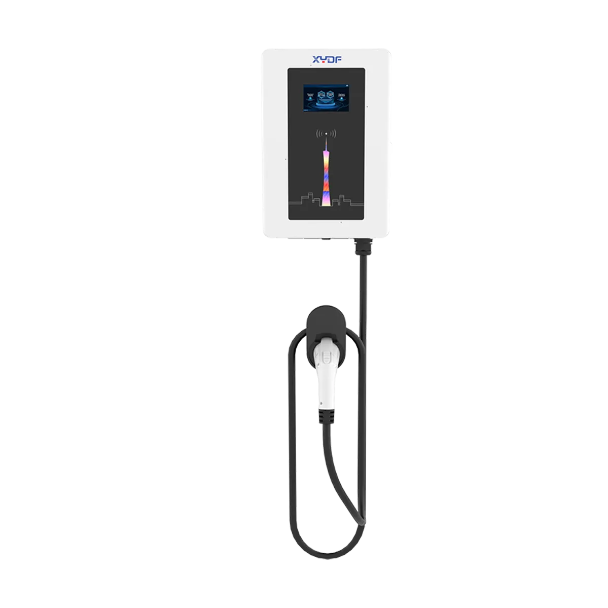
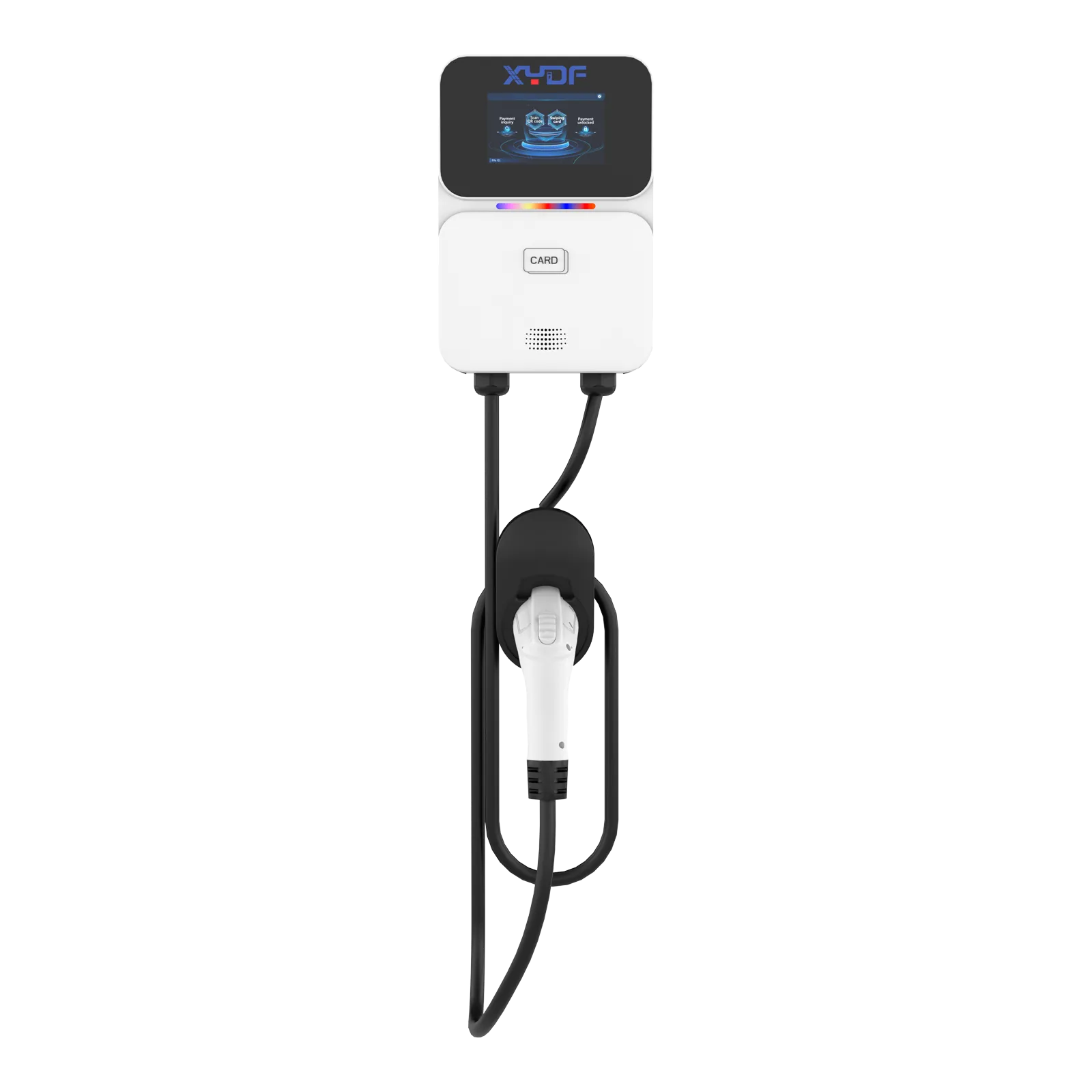
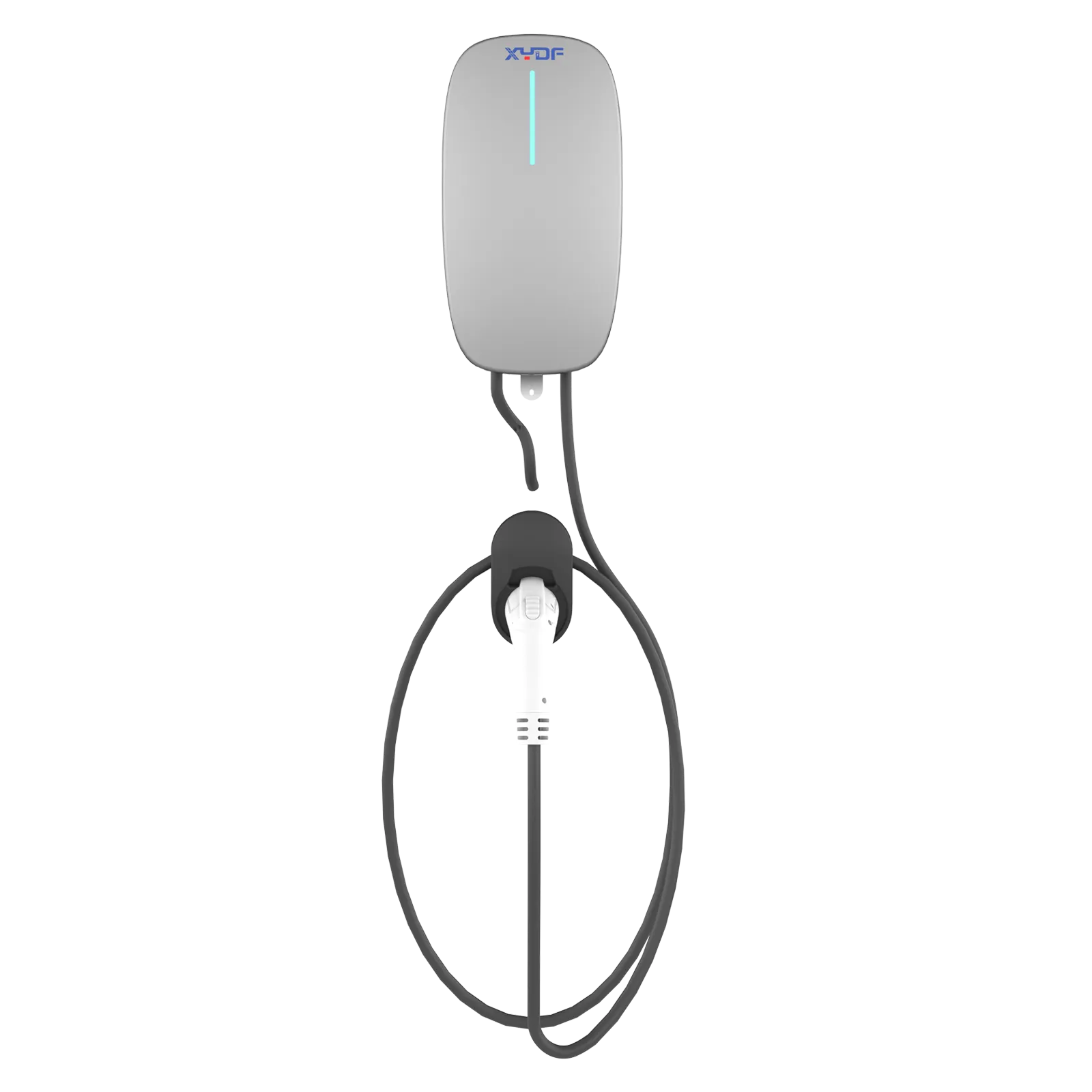
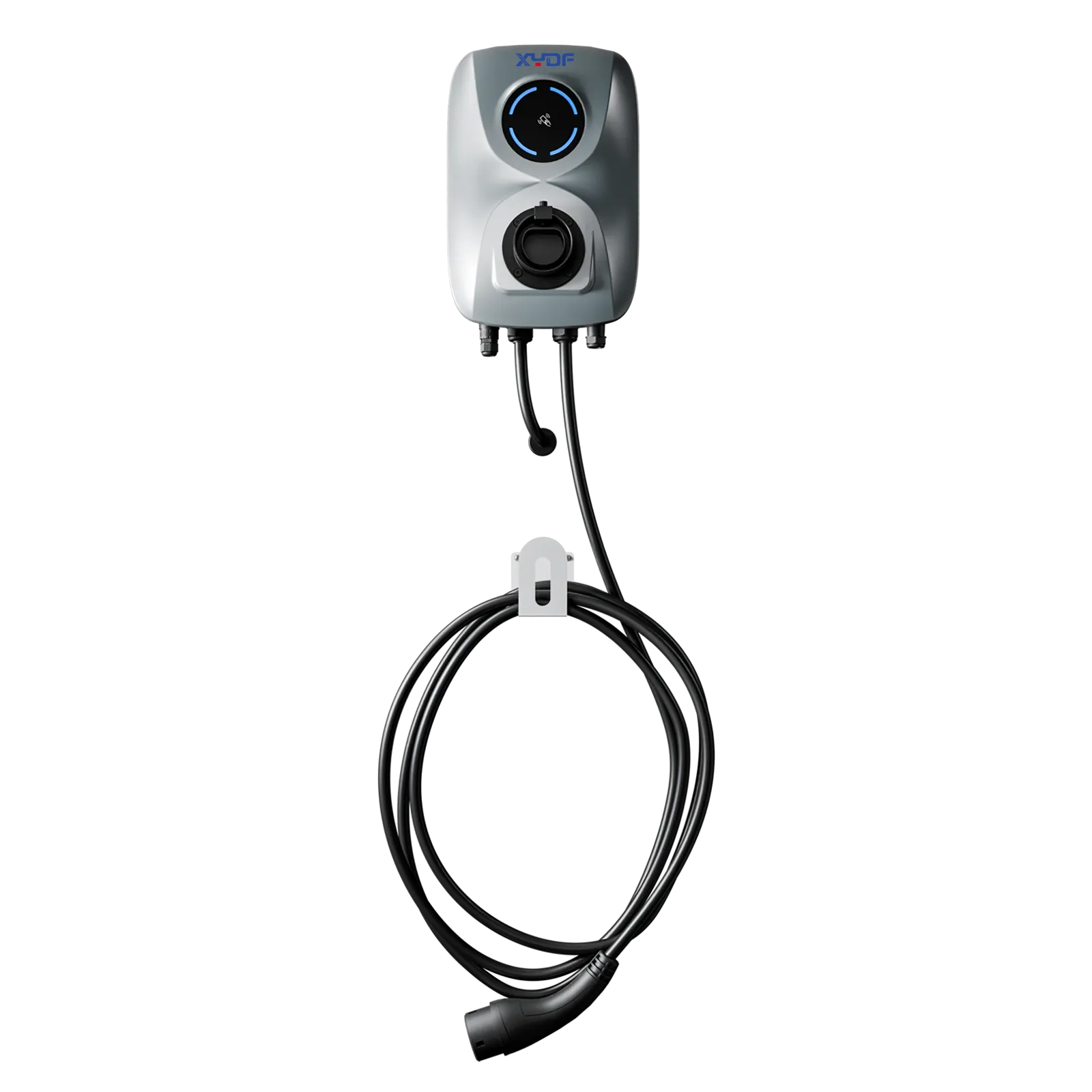
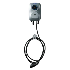
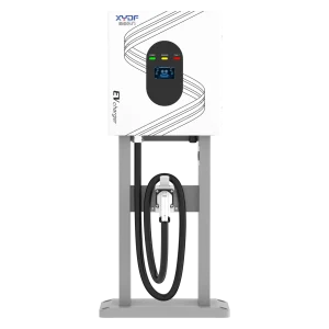
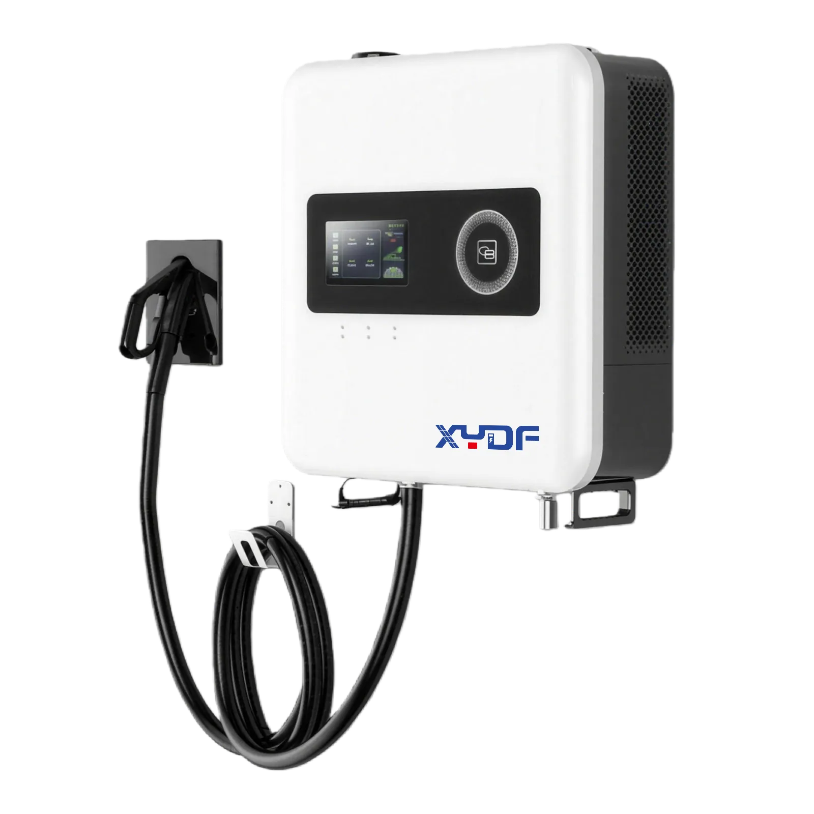
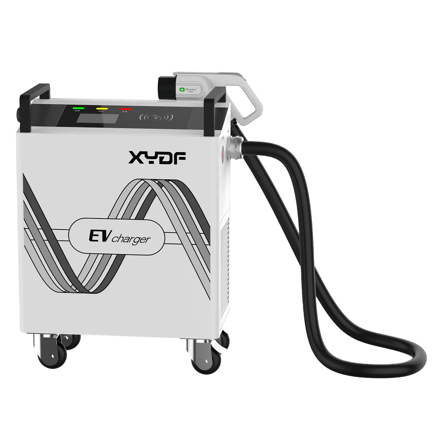
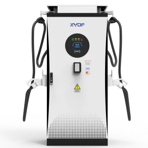
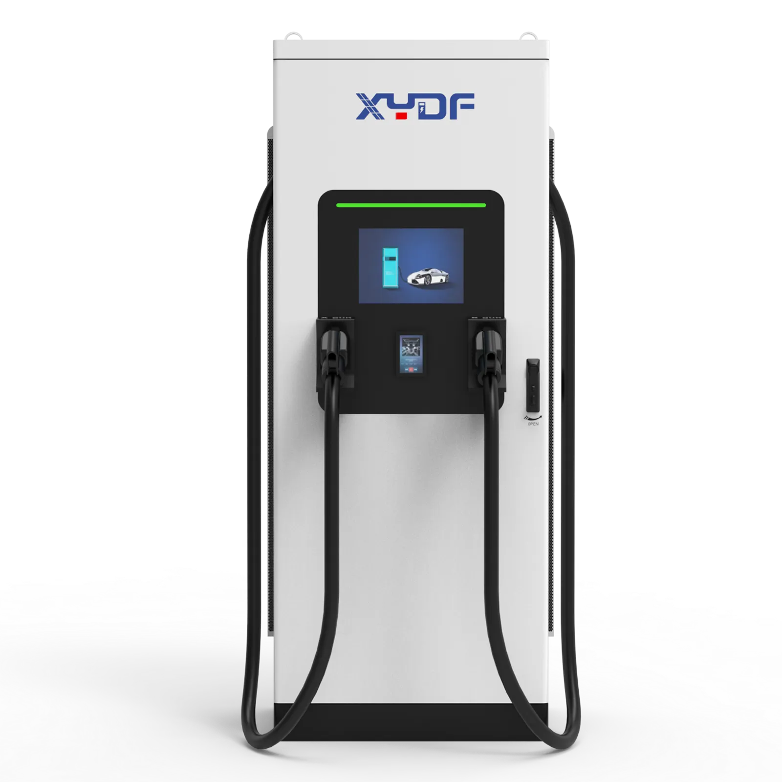
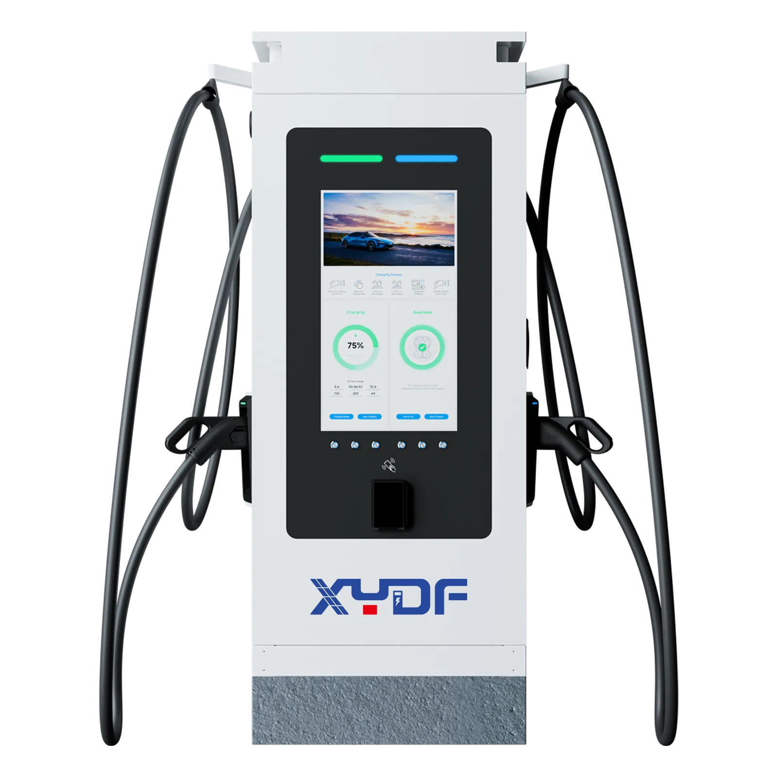
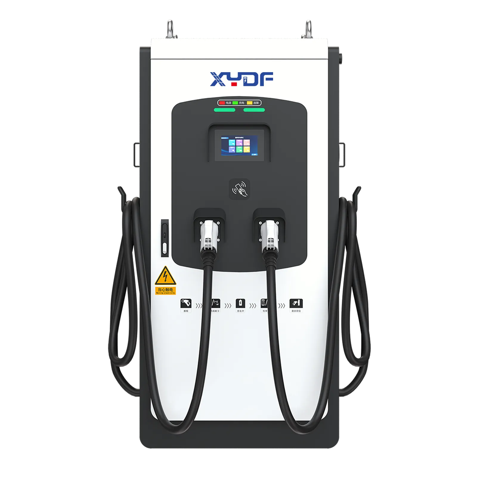
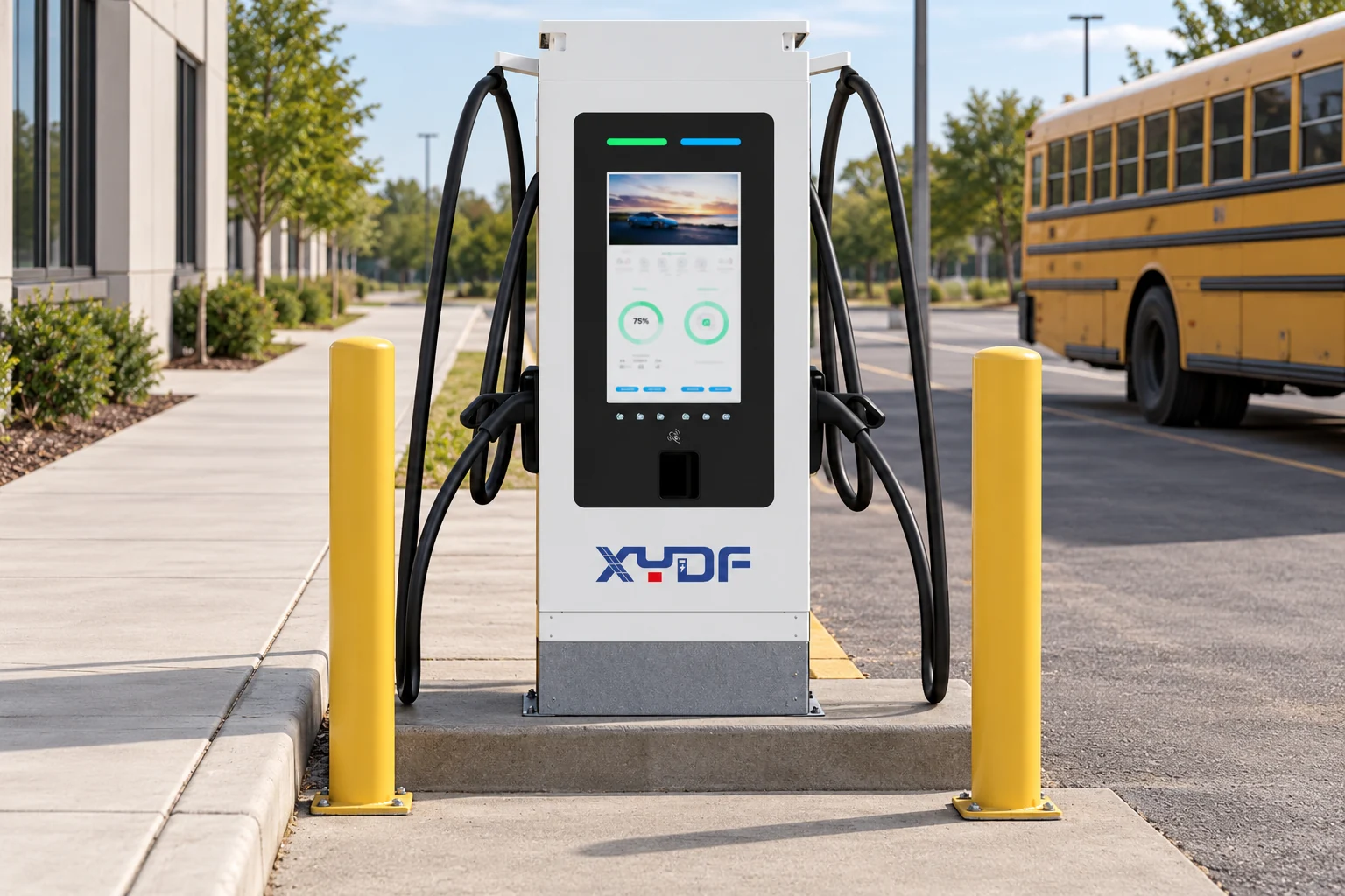
When assessing XYDF AC EV chargers and DC charging stations, request confirmation of voltage, connector, communication and power compatibility with the selected bus. The product families are starting points for a specification review, not evidence that every school bus can use every model.
Commission the system against a representative departure schedule, with several vehicles connected and the power cap active. Then test the agreed failure scenarios. Record the results and assign ownership of software updates, faults and expansion planning before the first full-service school day.
Frequently asked questions about school bus charging
How many chargers does an electric school bus depot need?
The answer depends on simultaneous parking, available charging windows and whether staff can move buses between connections. A dedicated connection per parked bus simplifies overnight scheduling, while shared power may reduce simultaneous demand. Count shared-cabinet failures when assessing backup capacity.
How should bus routes and departure times drive charger sizing?
Estimate the energy each route requires, the energy remaining on return and the reserve needed at the next departure. Divide the required addition by usable charging time, accounting for losses and the bus charging curve. Size the tightest operational cases rather than relying only on fleet averages.
Is overnight Level 2 or DC fast charging better for school buses?
Compatible AC charging can suit long overnight windows when the bus accepts enough AC power. DC charging may be appropriate for larger energy needs or shorter turnarounds. Confirm the actual bus interface and charging limits before choosing either approach.
How much utility capacity does a school bus depot require?
It depends on required energy, charging deadlines, simultaneous demand and other site loads. Use a managed charging simulation to develop the load profile, then have the utility and designer determine the service and equipment requirements. An average power calculation alone cannot size the electrical installation.
Can managed charging avoid simultaneous peak loads at a depot?
It can stagger starts and allocate power within a site limit when the available time is sufficient to meet all departure targets. The system also needs an agreed fallback during communication loss. It cannot compensate for a fundamental shortage of energy-delivery capacity.
What safety and traffic controls are needed for school bus charging?
Plan bus turning paths, cable storage, pedestrian access, equipment protection, lighting and emergency access. Define plug-in checks, fault reporting and safe isolation responsibilities. Apply the relevant local requirements and manufacturer instructions to the actual depot layout.
References
- WRI Electric School Bus Initiative: Charging infrastructure fundamentals
- WRI Electric School Bus Initiative: Range and reliability
- WRI Electric School Bus Initiative: Managed charging and V2X
- WRI Electric School Bus Initiative: Working with your electric utility
Build the depot around reliable daily departures
Effective school bus fleet charging infrastructure links route energy, vehicle compatibility, charging windows, utility capacity and a workable yard layout. Validate those relationships before choosing equipment, then test the complete operating schedule at commissioning. A well-planned depot gives the transport team a clear way to keep buses ready and handle exceptions as the fleet grows.
Preparing a school bus depot project? Contact XYDF with bus models, route energy estimates, parking times and the available electrical supply to discuss a suitable charging configuration.