 Xinya Dongfang Electricity Technology Co., Ltd.


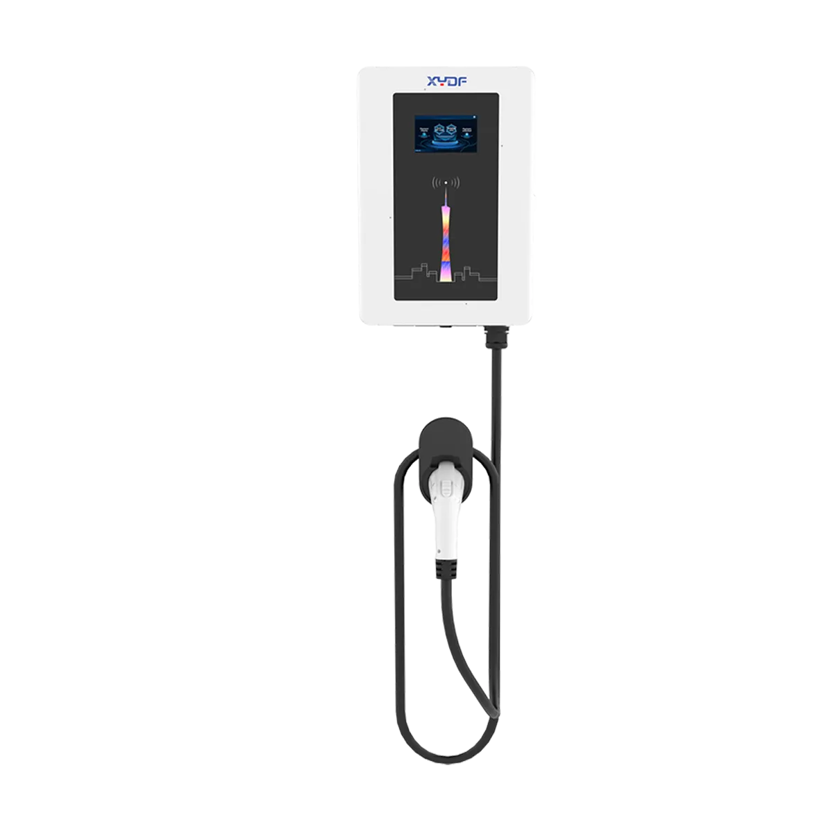
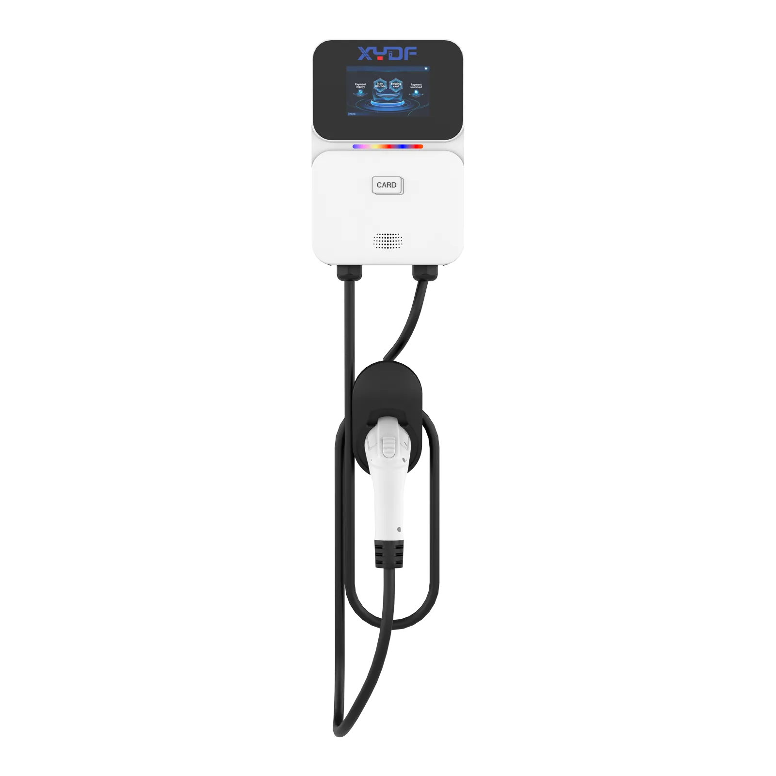
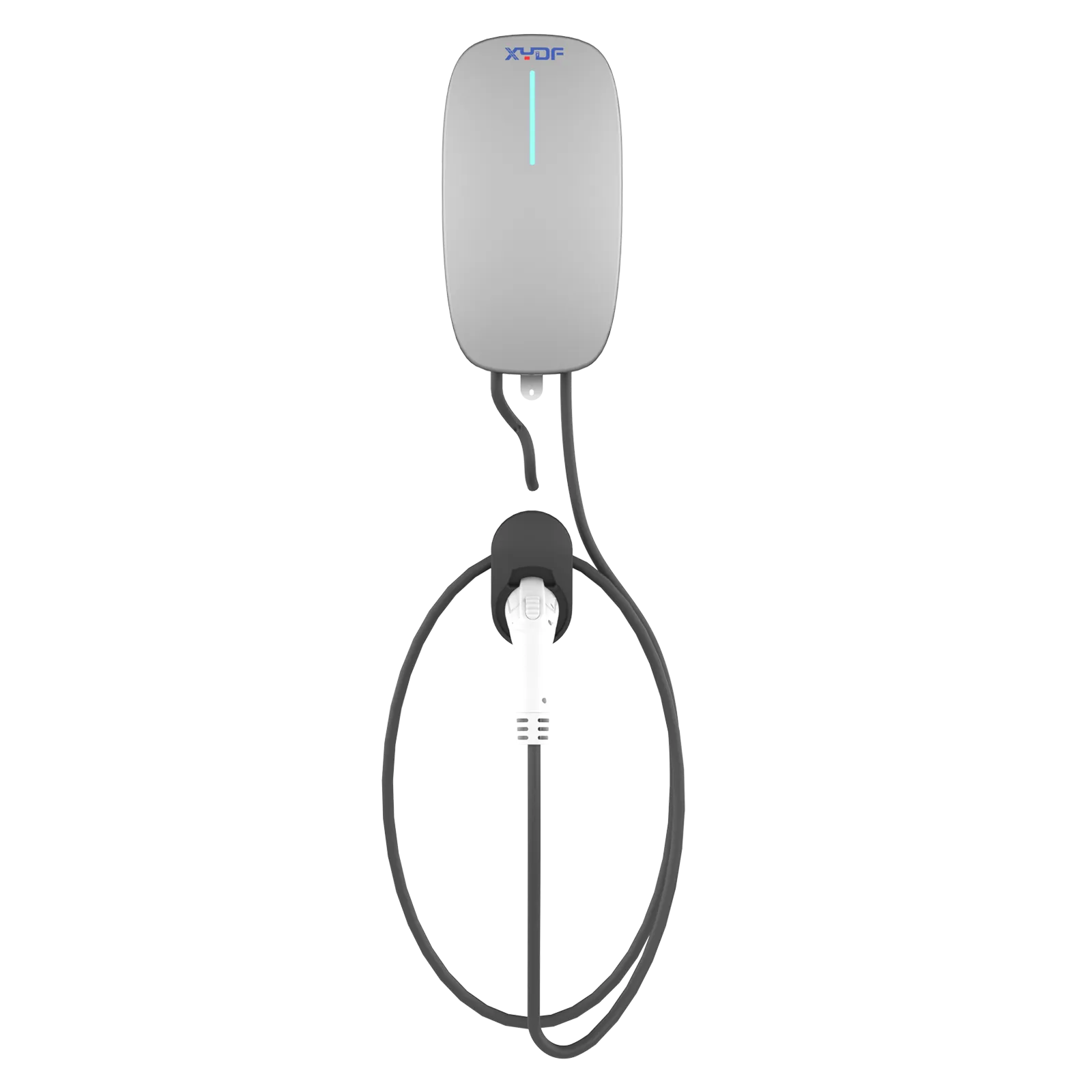
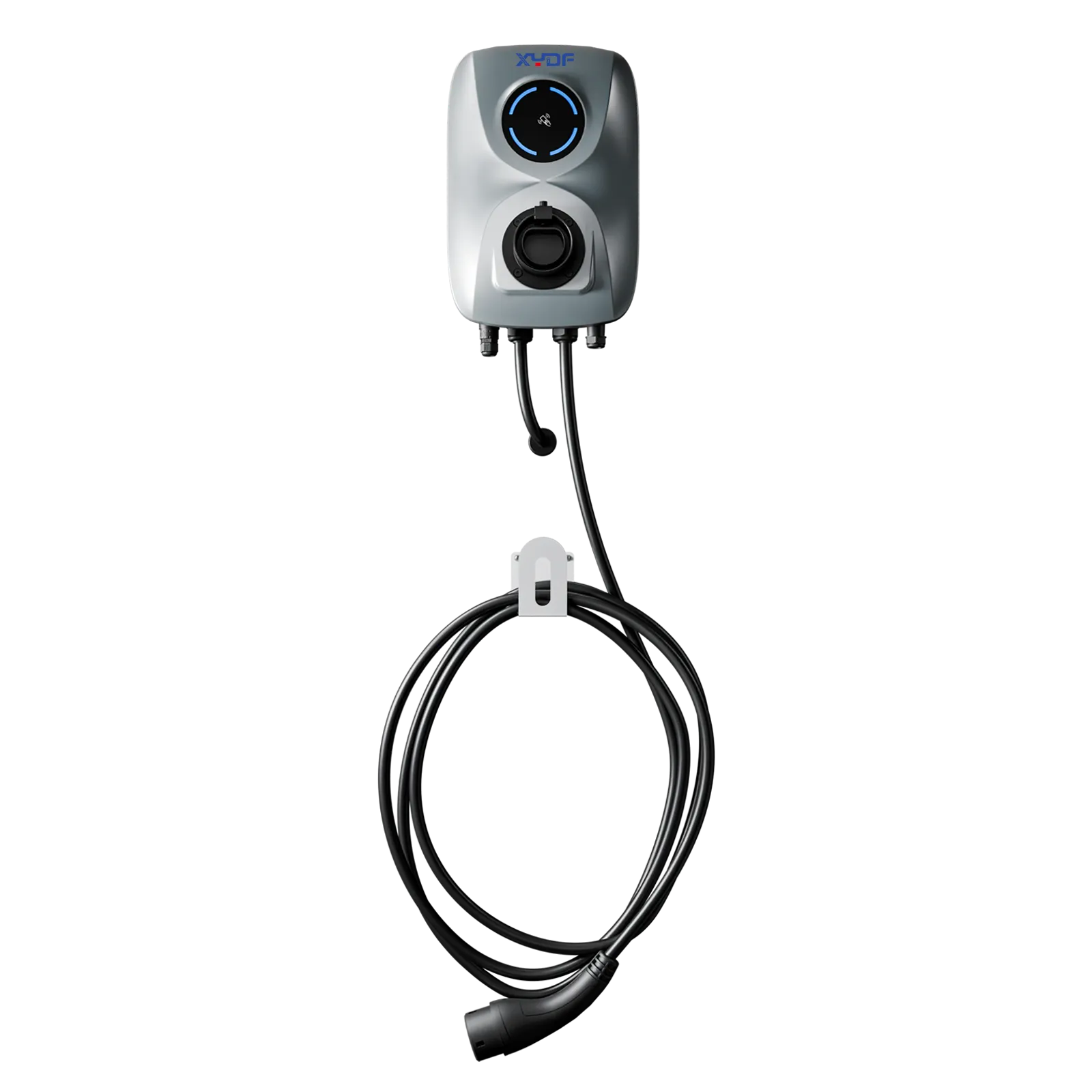
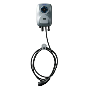
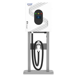

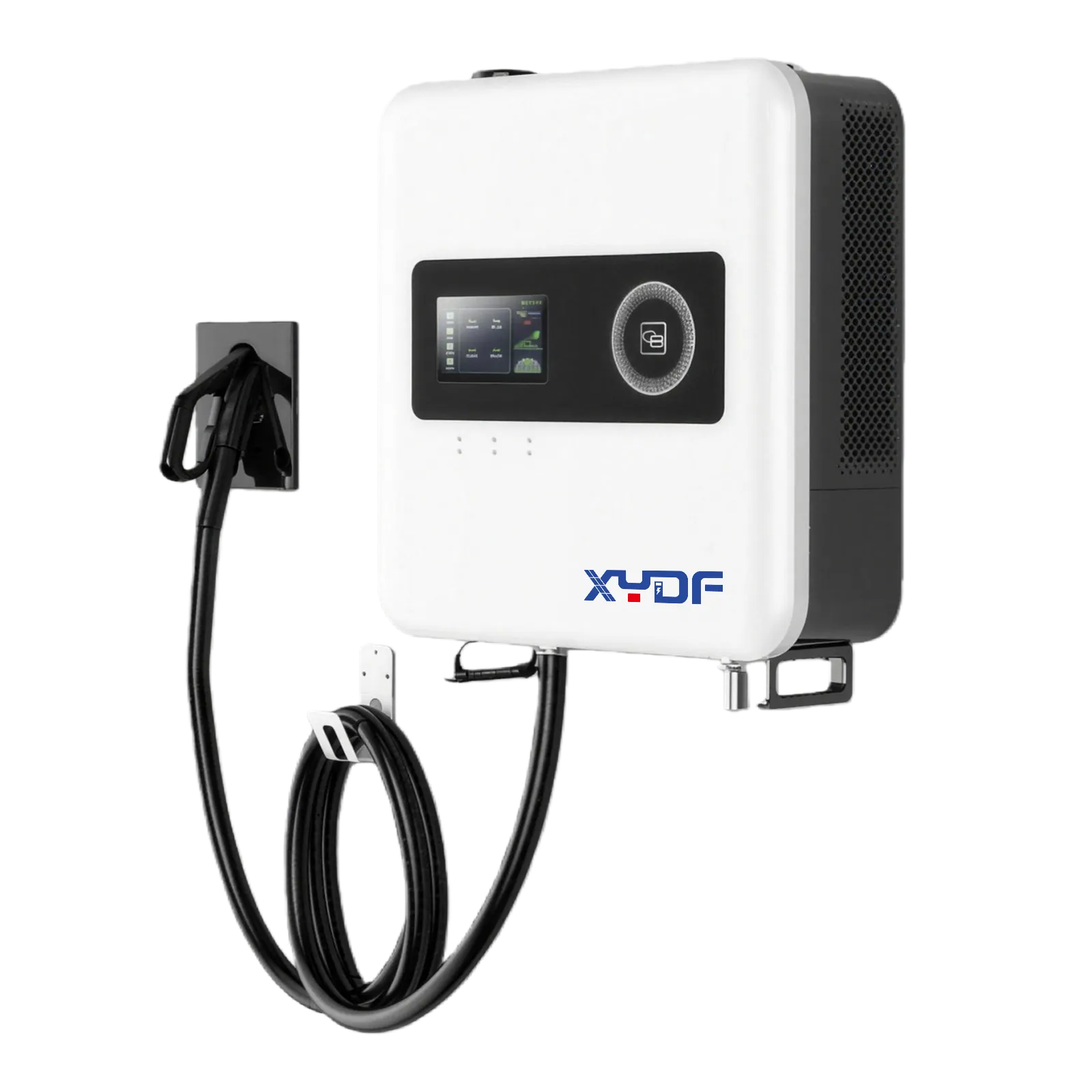
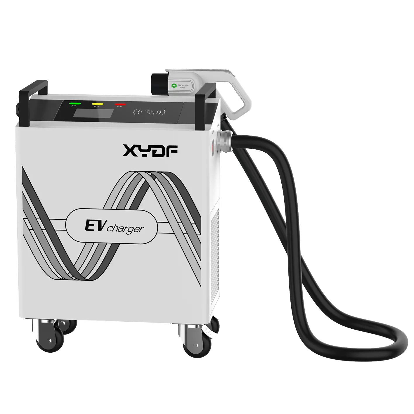
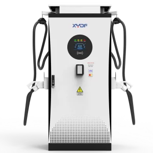
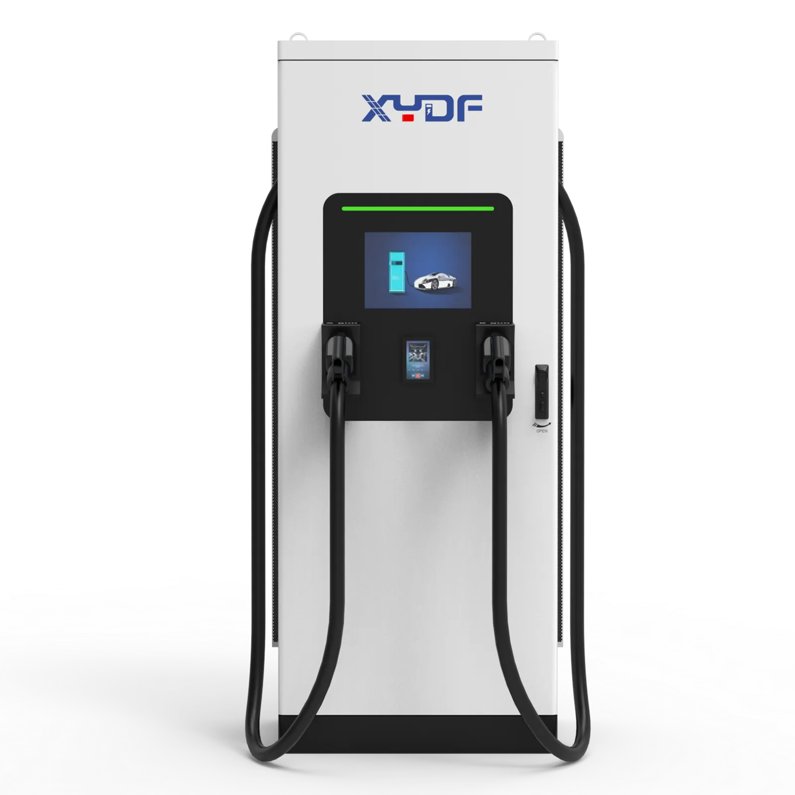
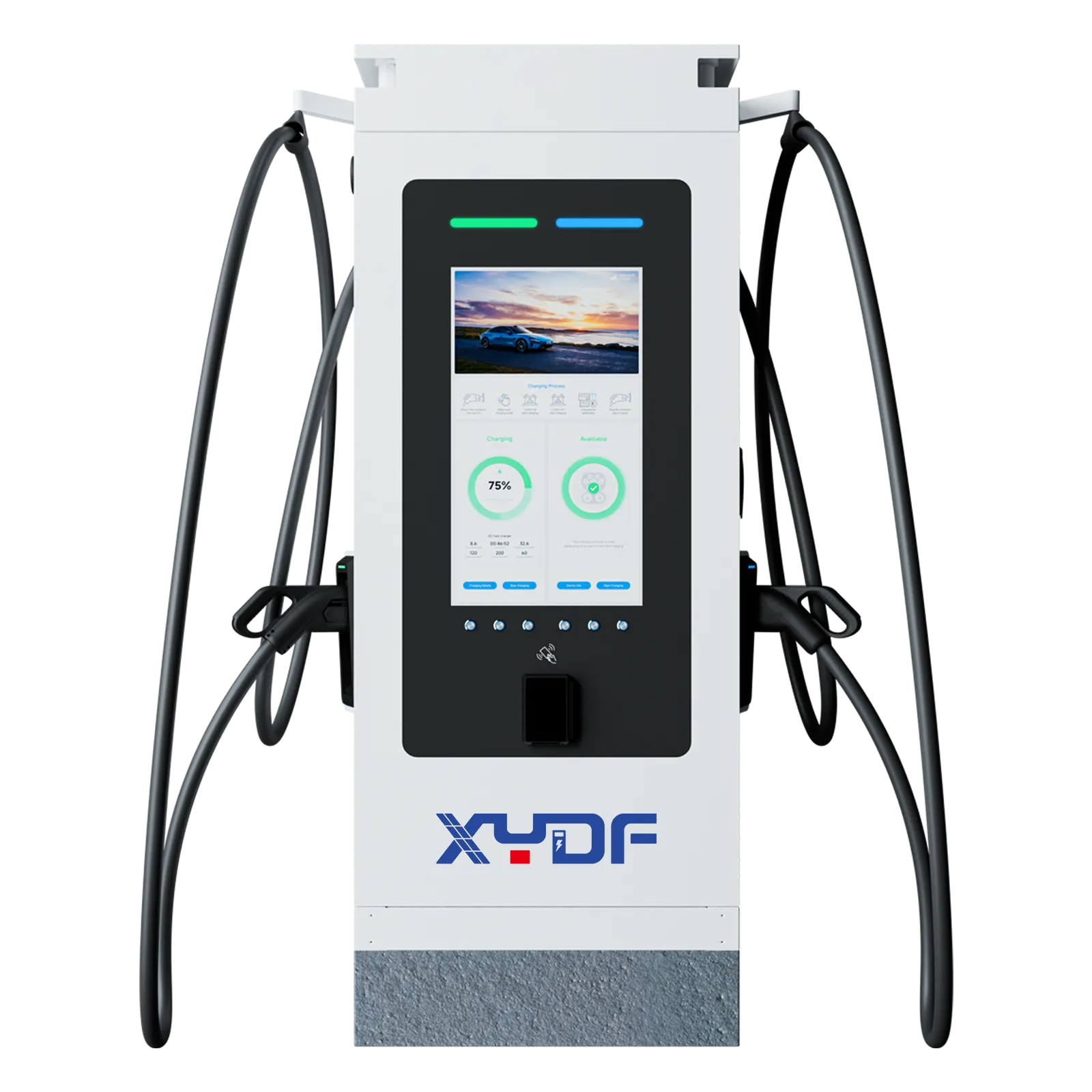
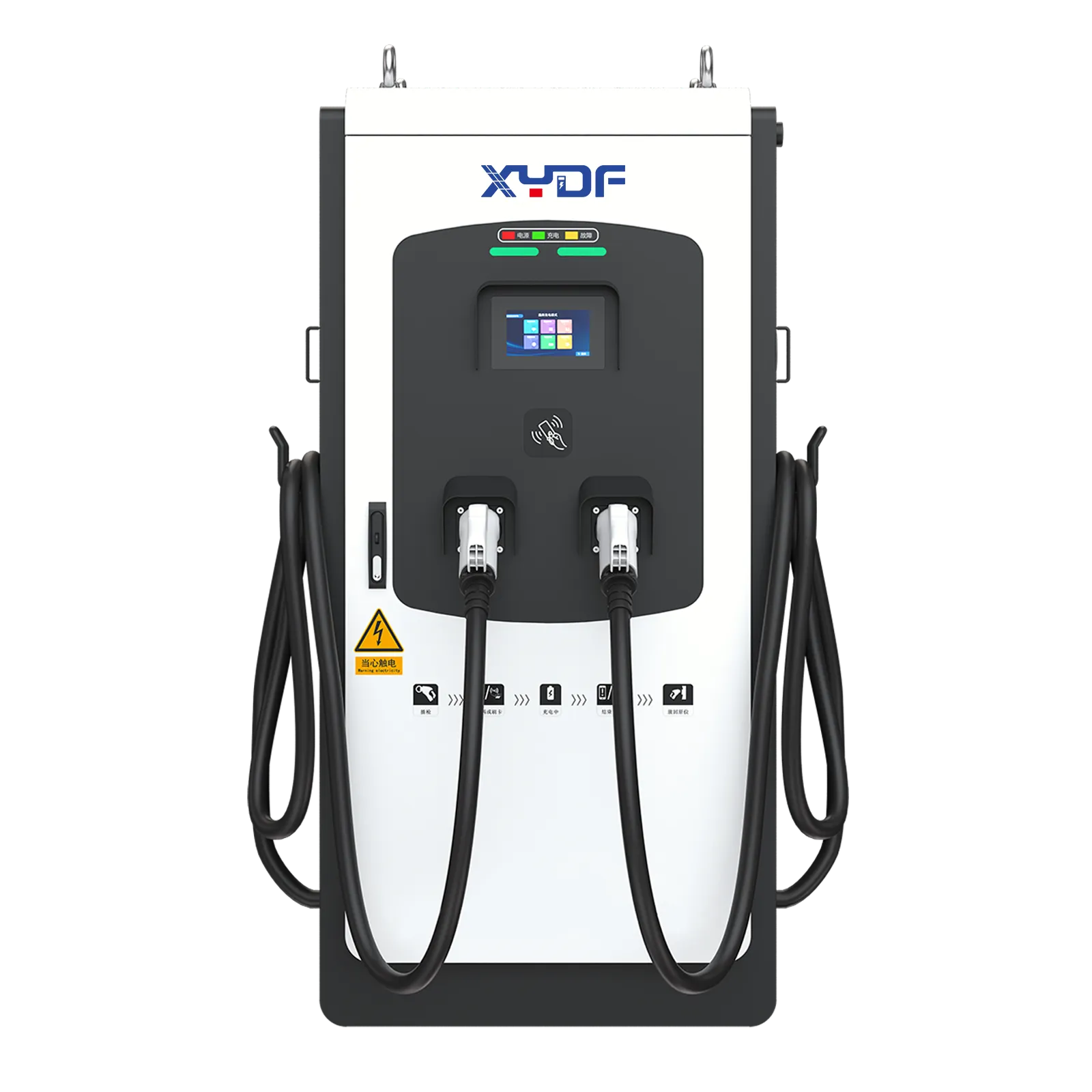
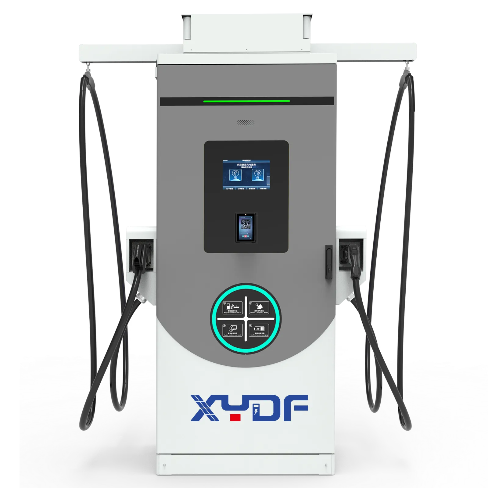
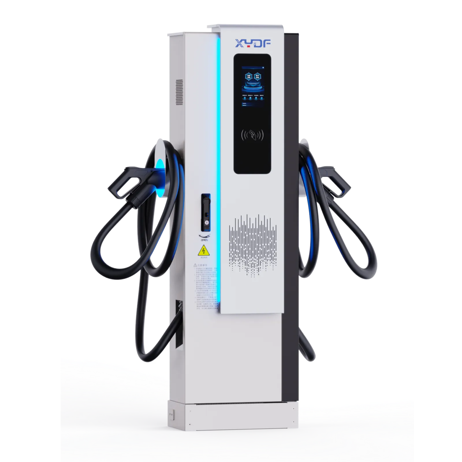
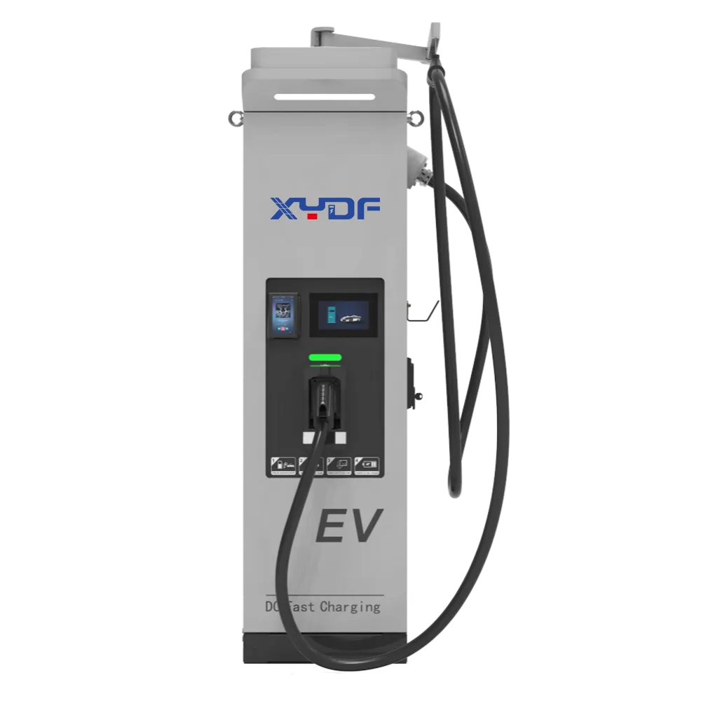
Automated and underbody charging changes the installation question from connector access to repeatable vehicle positioning, communication and recovery. The charger must work with the vehicle’s physical datum, bay geometry, alignment tolerance, control handshake, state-of-charge policy and dispatch schedule. If any of those interfaces is left undefined, a system can appear available while still missing the energy window required by an autonomous fleet. This guide explains the engineering and operating checks needed for port and terminal fleets, including commissioning, fault handling, maintenance access and safe manual recovery.
Automated port charging should be procured as a dispatch-connected system, not as an unattended plug. A 1 m positioning miss is not an engineering tolerance for an underbody coupler; the allowable window must be defined by the chosen connection mechanism and validated in representative weather and traffic conditions. For carregamento da frota de veículos elétricos, begin by mapping dwell time, energy per mission, vehicle position repeatability, and recovery procedures before selecting hardware. Use applicable electrical and vehicle-safety standards as design and test context, then require the supplier to document the specific product certifications needed for the destination market.
At ports, salt, spray, dust, heavy traffic, and time-critical dispatch create coupled risks. Underbody contacts, pantographs, and wireless systems can reduce manual intervention, but each brings different alignment, inspection, and power requirements. The right architecture depends on the vehicle, site rules, and cost of a missed mission—not a single charger specification.
Specify the operating loop before specifying the connector
Start with energy and dwell-time evidence
Measure energy per loaded and unloaded mission, queueing, auxiliary loads, and dwell opportunities. Illustratively, a tractor needing 180 kWh during a 10-hour shift with four 20-minute windows needs an average 13.5 kWh per window before losses and reserve. Battery acceptance, temperature, and power sharing can change the result. Evaluate a carregador rápido de corrente contínua comercial against the vehicle charge curve and site load profile, not only its nameplate output.
National Renewable Energy Laboratory resources underscore that planning must consider vehicle duty, charging power, and site electrical capacity together. At a port, add berth occupancy and dispatch consequences. IEC 61851-1 and IEC 61851-23 provide relevant conductive-charging context; standards references are not blanket product-certification claims.
Make dispatch integration explicit
A charge-management layer needs a clear authority model: the fleet system decides which vehicle may leave service, the charger reports readiness and delivered energy, and the terminal operating system receives only the status it needs. Define states such as approach, position-confirmed, connection-enabled, charging, charge-complete, fault, and manual recovery. Each state should have an owner, timeout, alarm route, and safe release action. This is where fleet ev charging creates value: a shorter unattended session is only useful when it can be scheduled without consuming a vehicle needed for the next job.
The acceptance question should be stated in operational terms: can the vehicle, bay, charger, and dispatch system recover from a failed connection without delaying the next move? Before choosing an interface, require a state-and-recovery matrix covering approach, position confirmation, connection, charge interruption, timeout, manual release, and return to service. ISO 3691-4 and IEC 61851-23 provide relevant safety and conductive-charging context, but the supplier still needs to prove the complete installation with the intended vehicle and site conditions.
Choose underbody charging around positioning and serviceability
Underbody conductive charging can suit vehicles that return repeatedly to fixed bays, but it concentrates risk at the vehicle-to-ground interface. Define vehicle reference point, approach direction, slope, height range, debris tolerance, drainage, and inspection access. Do not adopt a generic centimetre value: the final tolerance belongs in the interface-control document and site acceptance test.
ISO 3691-4 provides safety requirements and verification concepts for driverless industrial trucks and their systems; it does not certify a charging installation. Use it to structure the interaction hazard review alongside destination-market electrical requirements.
| Charging approach | Operational strength | Primary constraint | Maintenance consideration | Best-fit tendency |
|---|---|---|---|---|
| Automated underbody conductive contacts | Fast repeatable stops with no operator plug handling | Precise interface geometry and clean, drainable bay | Inspect contacts, alignment aids, and vehicle underside | Fixed-route autonomous vehicles with predictable stops |
| Automated pantograph or overhead contact | Connection hardware remains accessible above vehicle | Clearance, mast geometry, and overhead protection | Inspect moving contact and structural components | Buses or vehicles with controlled roof access |
| Manual conductive DC charging | Flexible and familiar hardware model | Requires people, safe cable handling, and process discipline | Inspect cable, connector, and strain relief | Mixed fleets or low-frequency backup charging |
| Wireless charging | No exposed conductive contact at the stop | Vehicle integration, alignment, and system efficiency trade-offs | Inspect pads and foreign-object controls | Purpose-designed vehicles where dwell is repeatable |
Design the port bay as a safety and uptime asset
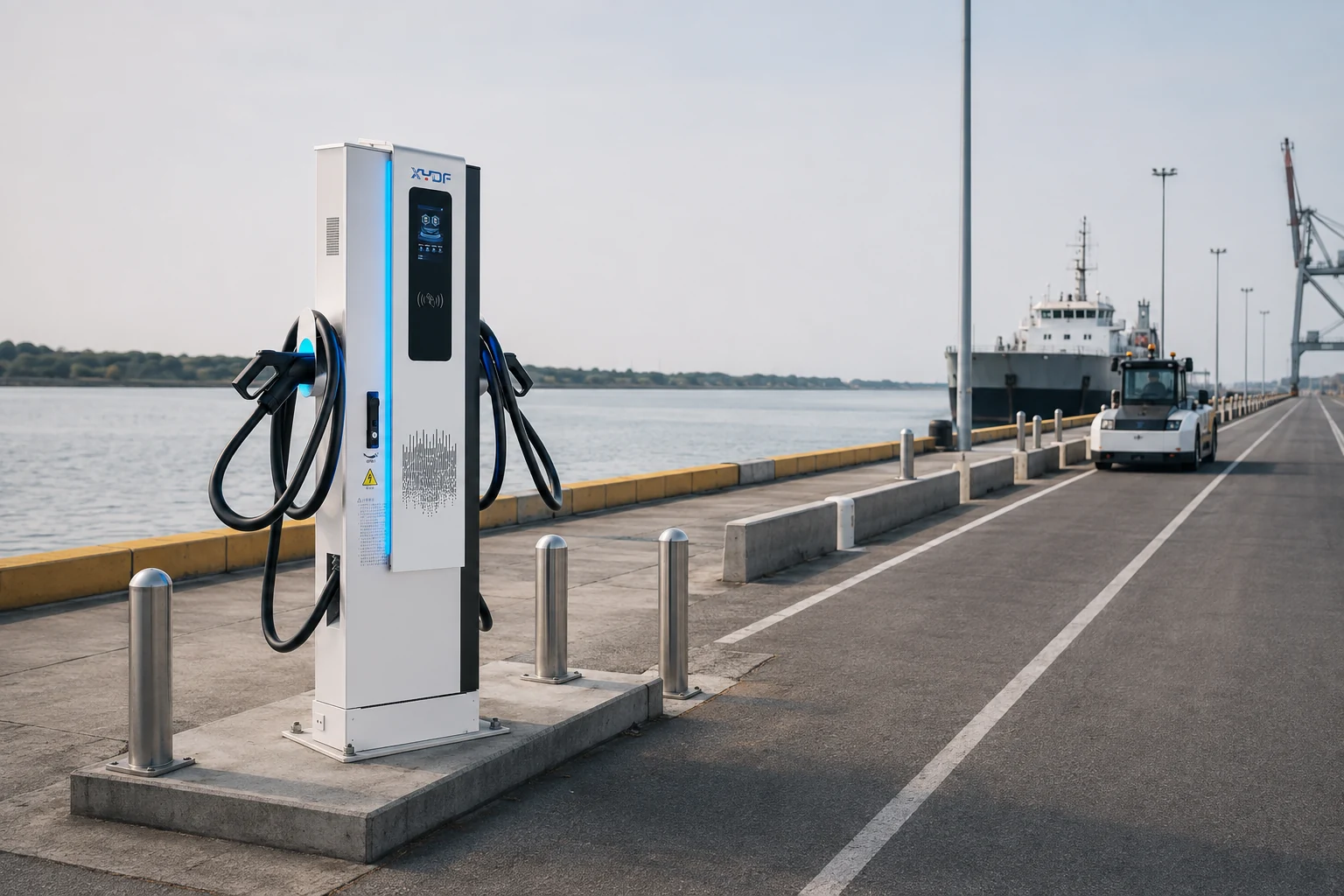
Port charging safety begins with vehicle segregation, bollards, contact protection, lighting, drainage, emergency isolation, technician access, and a manual bypass route. Salt-laden air and water make enclosure selection and maintenance critical. IEC 60529 defines IP-code classifications and test methods; an IP rating alone does not prove whole-workflow suitability for a quay or washdown practice.
Commissioning should include representative wet-weather and contamination scenarios within the manufacturer’s instructions and site rules. Record charge-start success, positioning retries, energy delivery, fault category, and recovery time by bay. The goal is safe, visible exception handling—not a promise of zero exceptions.
| Dimensão do design | Questions to ask | Illustrative acceptance evidence | Commercial consequence if ignored |
|---|---|---|---|
| Positioning repeatability | What vehicle datum and allowable approach envelope are specified? | Site trials across representative loads, turns, and bay conditions | Retries, contact damage, or manual interventions |
| Power architecture | How many vehicles can charge simultaneously and at what managed power? | Load study, protection coordination, and power-sharing logic | Demand charges, curtailment, or under-delivered energy |
| Environmental exposure | What salt, water, dust, and drainage conditions are expected? | Documented enclosure, material, inspection, and cleaning requirements | Accelerated corrosion and availability loss |
| Dispatch recovery | Who responds when positioning or charging times out? | Timed drill with alarm ownership and manual-release procedure | Missed moves and unsafe ad-hoc workarounds |
| Interoperabilidade | Which vehicle, charger, and control protocols are in scope? | Interface-control document and witnessed integration testing | Costly late-stage software or hardware changes |
Match high-power DC charging to fleet rhythm and grid limits
A high power ev charging station can recover energy during short dwell windows, yet high power is not automatically high availability. Battery limits, interface rating, transformer capacity, protection studies, and concurrent load determine delivered power. A conventional carregador rápido DC may fit a longer maintenance dwell; model both cases against missions and reserve.
Calculate total cost of ownership from electrical and civil work, controls integration, spares, inspections, lost mission cost, and tariff exposure—not only equipment price. Illustratively, saving one 10-minute intervention per vehicle per day helps only if released time improves throughput or avoids another vehicle. Use measured post-commissioning data before assigning a return.
Procurement actions that reduce integration risk
- Issue a joint vehicle–charger–site interface-control document before purchase order, including mechanical datums, electrical interface, communications, and fault states.
- Require a staged factory and site acceptance plan; document what is witnessed, the test conditions, pass criteria, and remediation route.
- Ask for destination-market certificates and declarations for the exact model and configuration. A test report, an IP test method, and a standards reference are not interchangeable product certifications.
- Specify service access, spare-parts lead times, cleaning intervals, corrosion checks, and a manual recovery process in the operating procedure.
XYDF can be considered when a project needs configurable ev charging systems and clear interface, testing, and documentation discussions. Buyers should validate vehicle compatibility, local approvals, site design, and service responsibilities.
Perguntas frequentes
O que é a carga automática para frotas autônomas?
A carga automática é um processo no qual um veículo chega a uma vaga definida, confirma a posição e as condições de segurança, se conecta ou permite a transferência de energia sem necessidade de manipulação manual de cabos, e informa o status aos controles da frota. Esse processo pode utilizar contatos condutivos, interfaces aéreas ou transferência sem fio. O mecanismo de carregamento deve ser integrado aos controles do veículo e a procedimentos de recuperação seguros.
Quando uma frota autônoma precisa de carregamento no subchassis?
O carregamento sob a carroceria é mais relevante quando os veículos retornam a pontos fixos com frequência, a manipulação manual do plugue é um gargalo e o veículo pode suportar uma interface definida sob a carroceria. Não é automaticamente preferível para tipos de veículos mistos, estacionamento irregular ou locais onde o acesso à parte inferior da carroceria seja difícil de inspeccionar. Confirme o envelope do veículo, o processo de drenagem e limpeza antes de selecioná-lo.
A recarga automática funciona em ambientes com chuva e em portos?
Ela pode ser projetada para uso em ambientes externos, mas a adequação depende da instalação completa: gabinete, contatos, drenagem, materiais, controles, manutenção e regulamentos elétricos locais. Os operadores portuários devem validar condições climáticas e de contaminação representativas durante testes de aceitação. Não se deve inferir a adequação de todo o sistema apenas com base na classificação IP do gabinete.
Qual a precisão que deve ter o posicionamento do veículo para a carga no assoalho inferior?
A precisão exigida é determinada pelo design mecânico e elétrico da interface selecionada, e não por um número universal. O fornecedor, o integrador de veículos e a equipe do local devem documentar o envelope de posição e altura permitido, e então comprovar isso com ensaios repetidos no local. Teste a trajetória real de aproximação, os estados de carga do veículo e cenários de posição comprometida.
A recarga rápida em DC é adequada para operações de frota autônoma?
Sim, quando o veículo aceitar a potência prevista e a frota tiver janelas de espera que justificam isso. É especialmente útil para cargas de oportunidade previsíveis, mas deve ser planejada com limites de capacidade da bateria, capacidade da rede, compartilhamento de energia e prioridades de despacho. Compare a energia entregue por janela de carga, em vez de depender apenas do valor da placa do carregador.
Como um porto pode gerir a carga sem perturbar a gestão da frota?
Reservar espaços de carregamento através da lógica de controle da frota, definir um limite mínimo de energia para a próxima missão e definir o que acontece quando um posto de carga ou veículo apresentar falhas. Monitorar as tentativas de recarga e o tempo de recuperação como KPIs operacionais, juntamente com a energia entregue. Na prática, o carregamento eficiente em frotas depende tanto da gestão de exceções quanto de sessões de carga bem-sucedidas.
Como um porto deve lidar com uma tentativa de conexão automatizada que falhou?
Treat a failed connection as a controlled exception: stop movement, isolate the charging interface, alert the dispatcher, and apply a documented retry limit before manual recovery. Log the vehicle position, connector state, weather, obstruction and recovery time. A fallback plug-in bay or supervised recovery process should be sized from the port’s actual failure and maintenance policy, not assumed to be available.
A carga automática do chassi elimina a necessidade de um método de carga de reserva?
No. Automated charging can reduce routine plug handling, but it does not remove the need for a recovery path when positioning, communications, vehicle access or the coupler is unavailable. Define which vehicles can use a manual connector, how a bay is released, and who authorises the intervention before the system is accepted.
What evidence should a port require before accepting automated charging?
Require a witnessed vehicle–bay–charger acceptance plan with repeatable positioning tests, charge-start success, fault-state handling, manual recovery, delivered energy, and recovery time. The evidence should identify the tested vehicle and configuration, site conditions, pass criteria, and owner for each exception; a standards reference or cabinet test report alone does not prove dispatch readiness.
References and next step
- ISO 3691-4: Industrial trucks — Safety requirements and verification — Part 4: Driverless industrial trucks and their systems.
- IEC 61851-23: Electric vehicle conductive charging system — Part 23: DC electric vehicle charging station.
- IEC 60529: Degrees of protection provided by enclosures (IP Code).
- U.S. National Renewable Energy Laboratory, Sustainable Transportation resources.
- IEC 61851-23 (scope checked 2026-10-06)
The durable design principle is simple: the charger, vehicle, bay, and dispatcher either recover energy as one operating system, or they create a new source of delay. For a procurement conversation about port-duty charging configurations, documentation, and integration questions, explore XYDF’s EV charging products and contact the team.