 Xinya Dongfang Electricity Technology Co., Ltd.


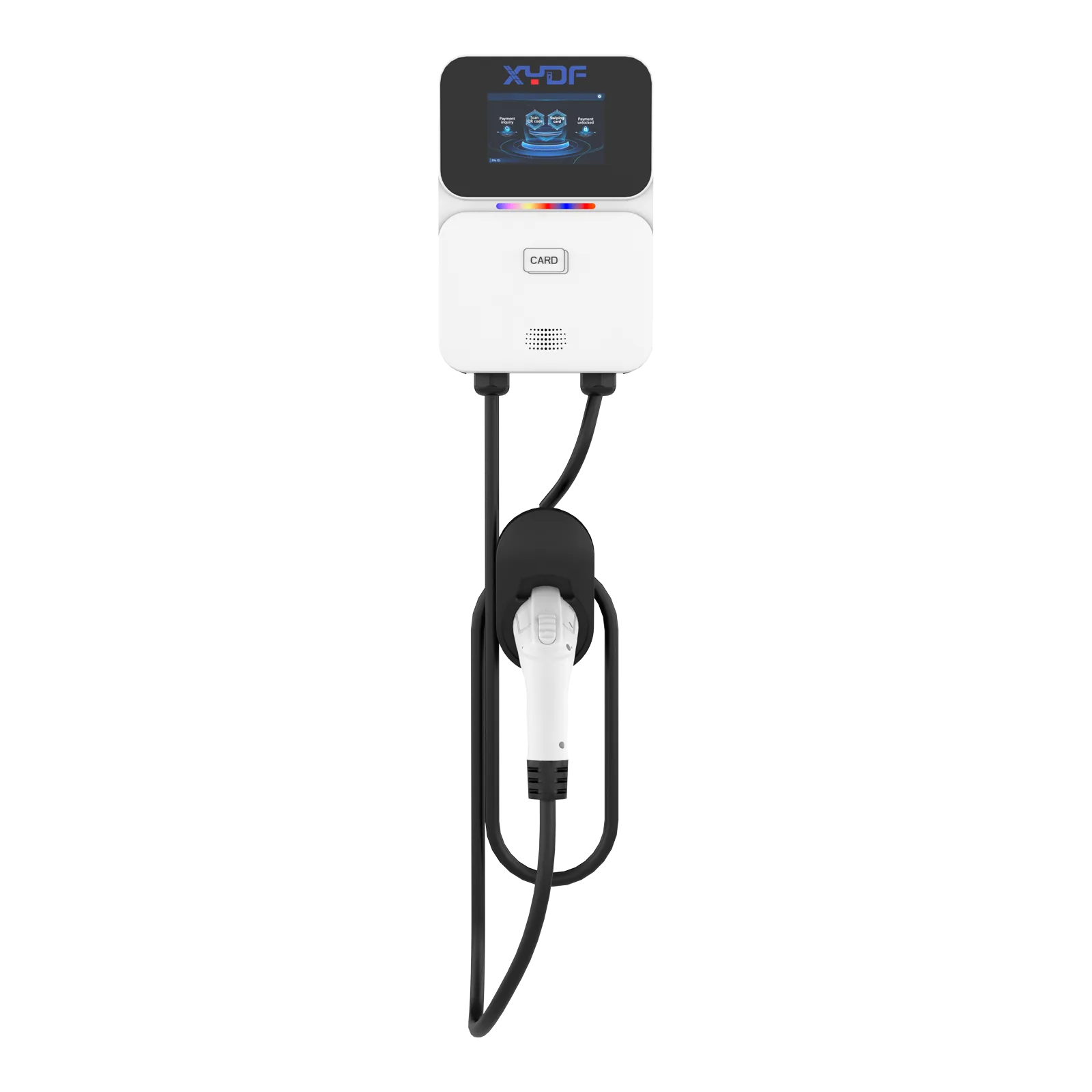
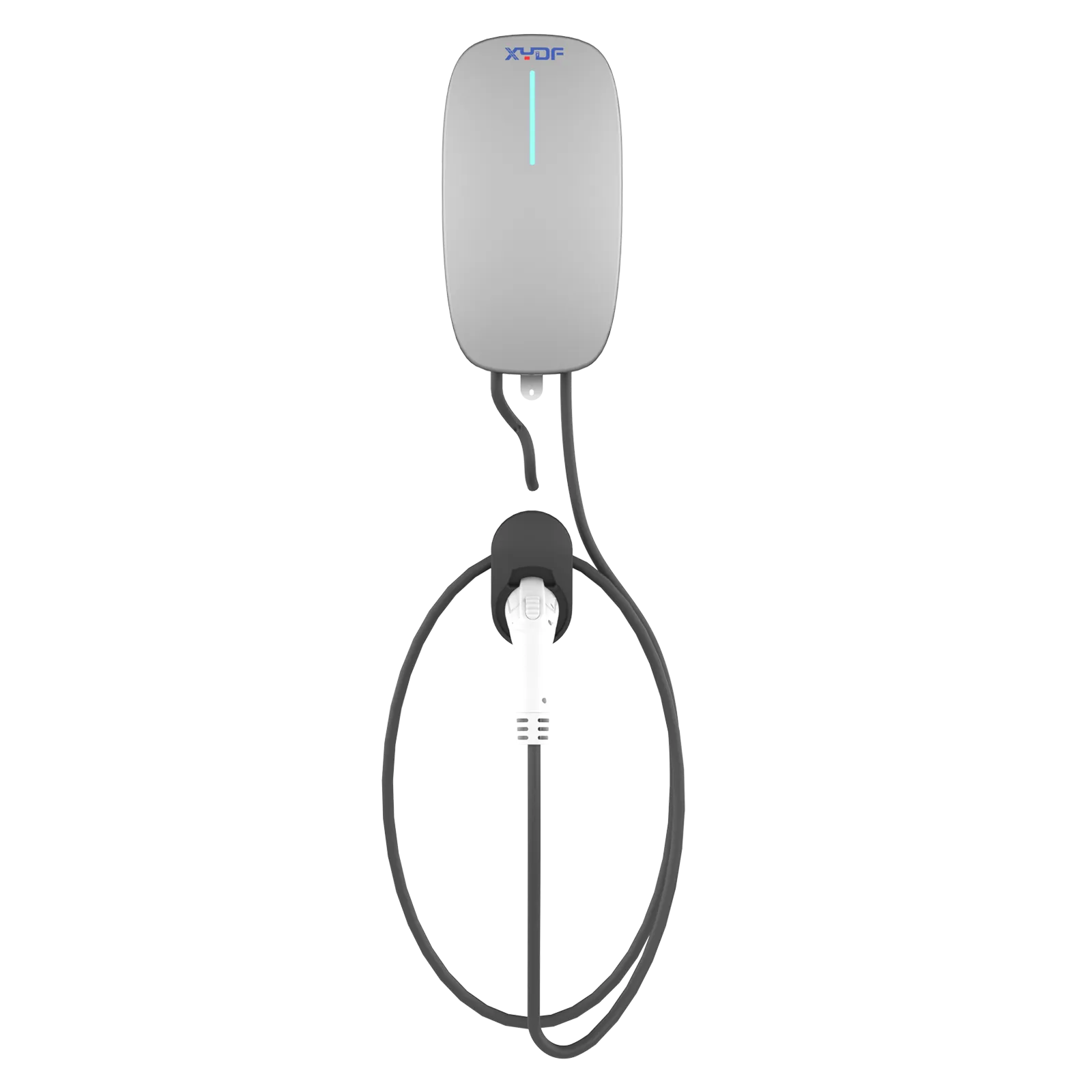
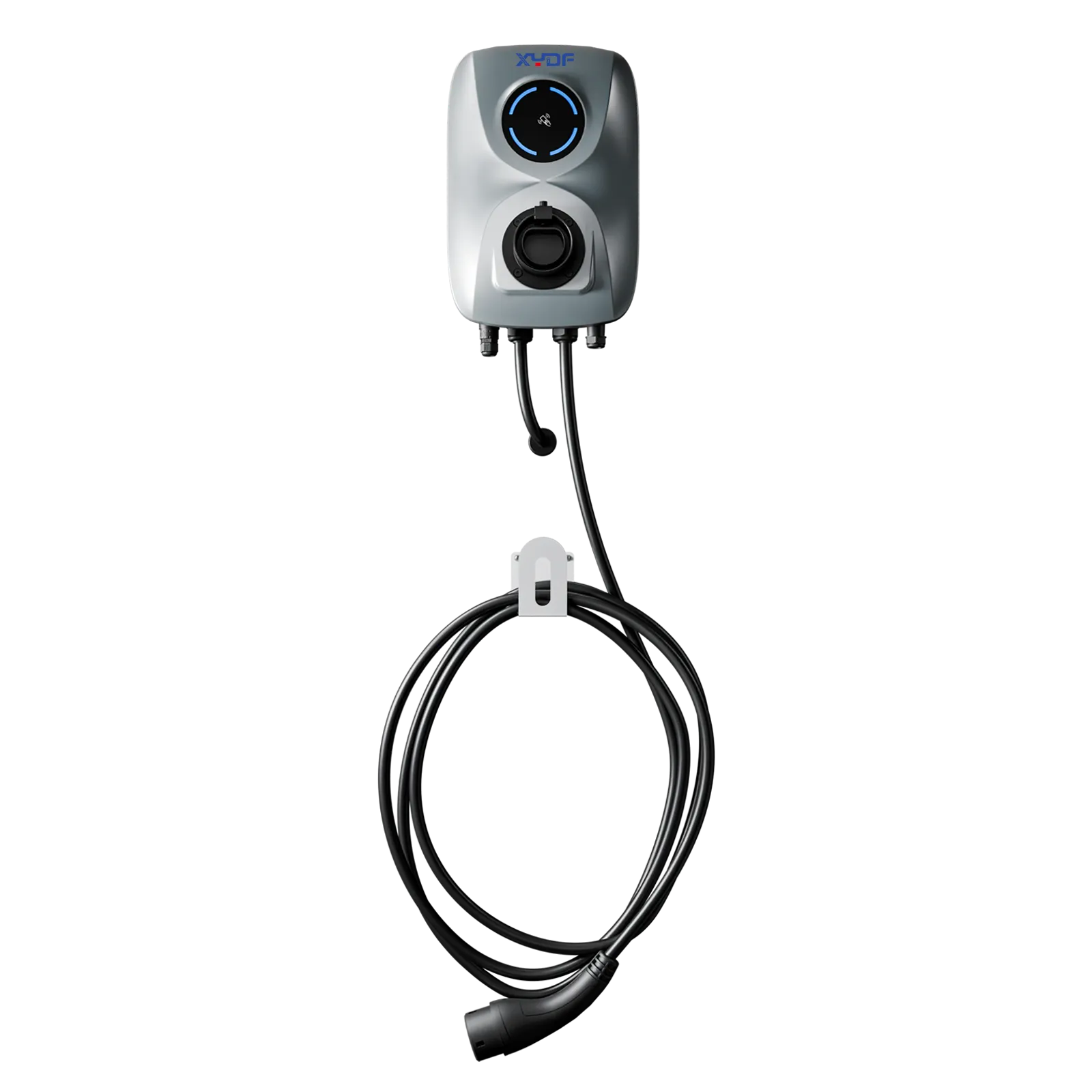
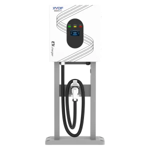

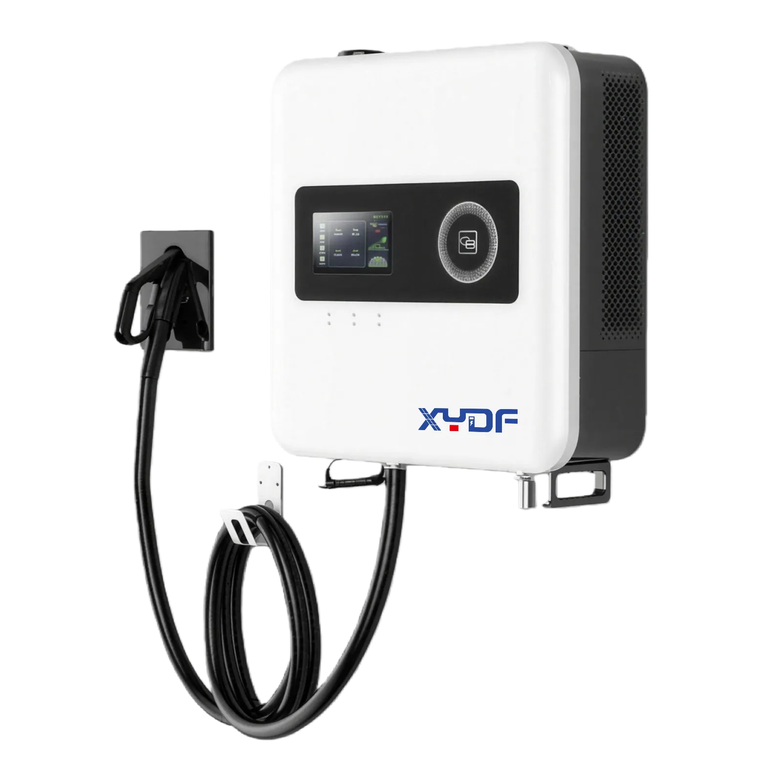
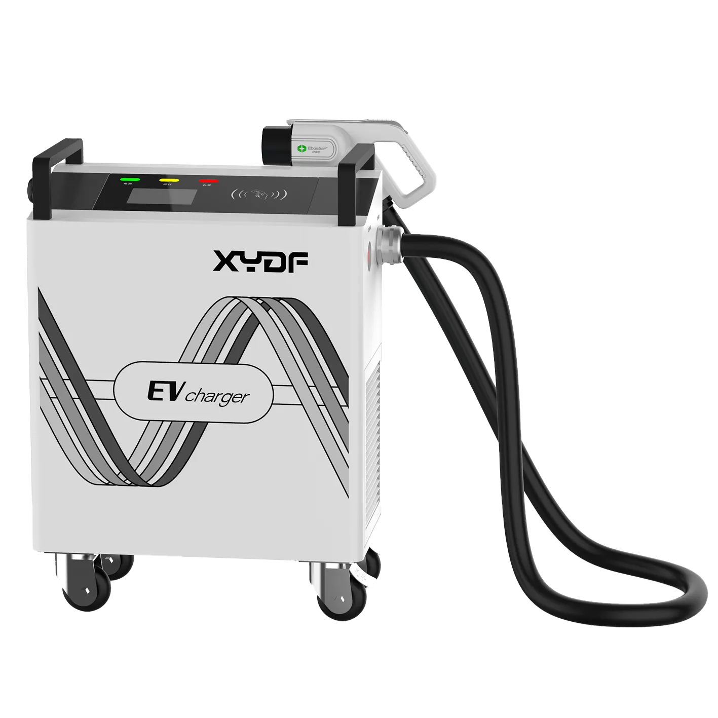
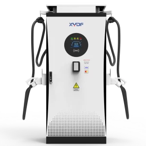
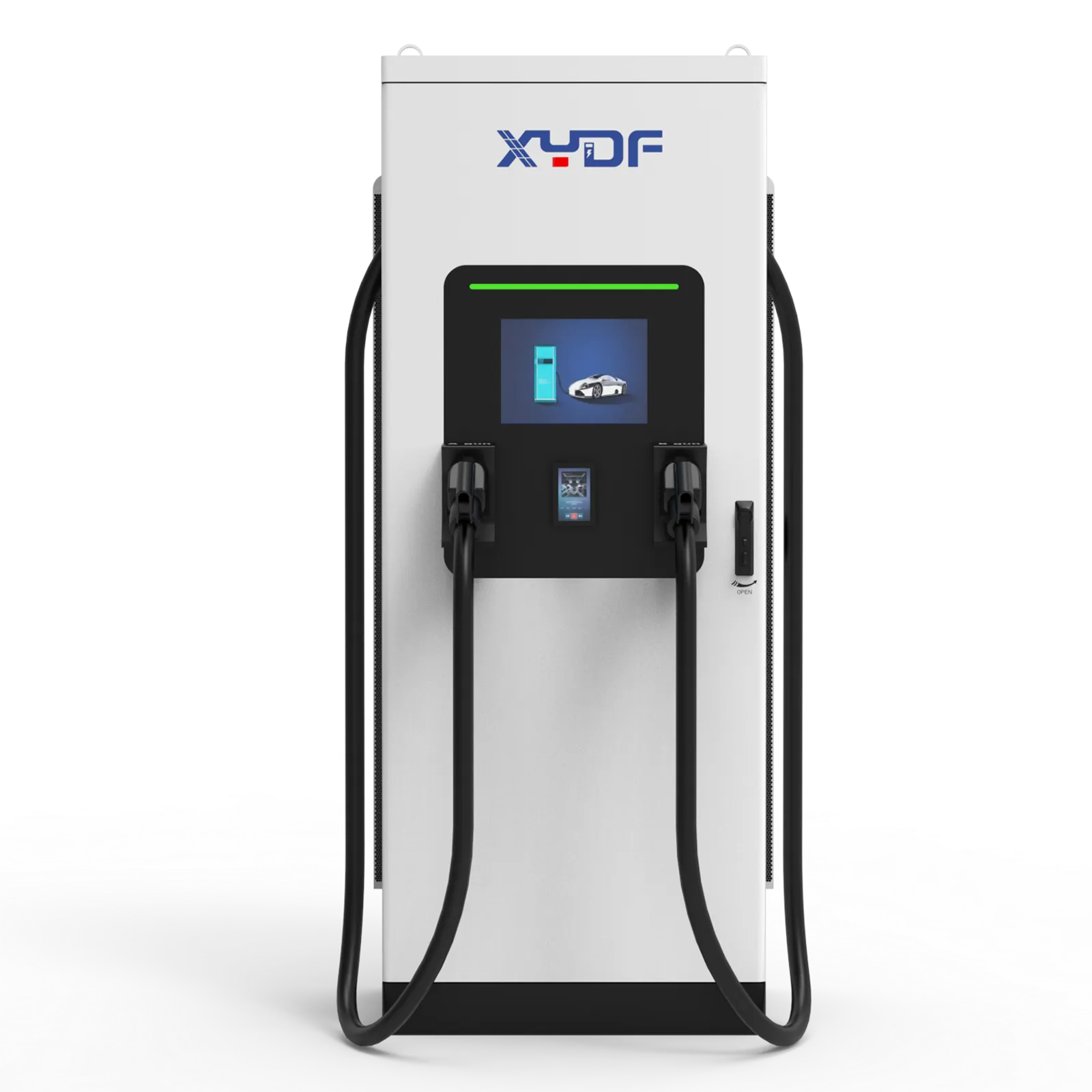
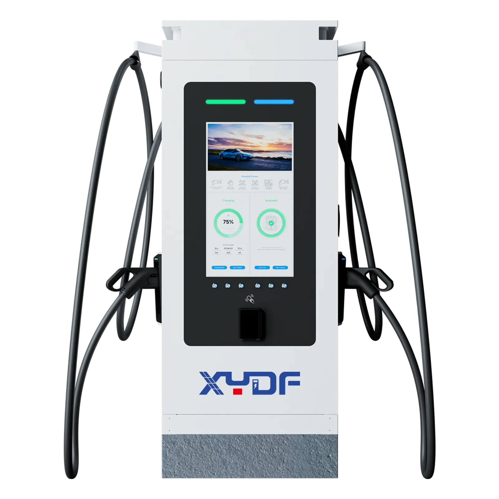
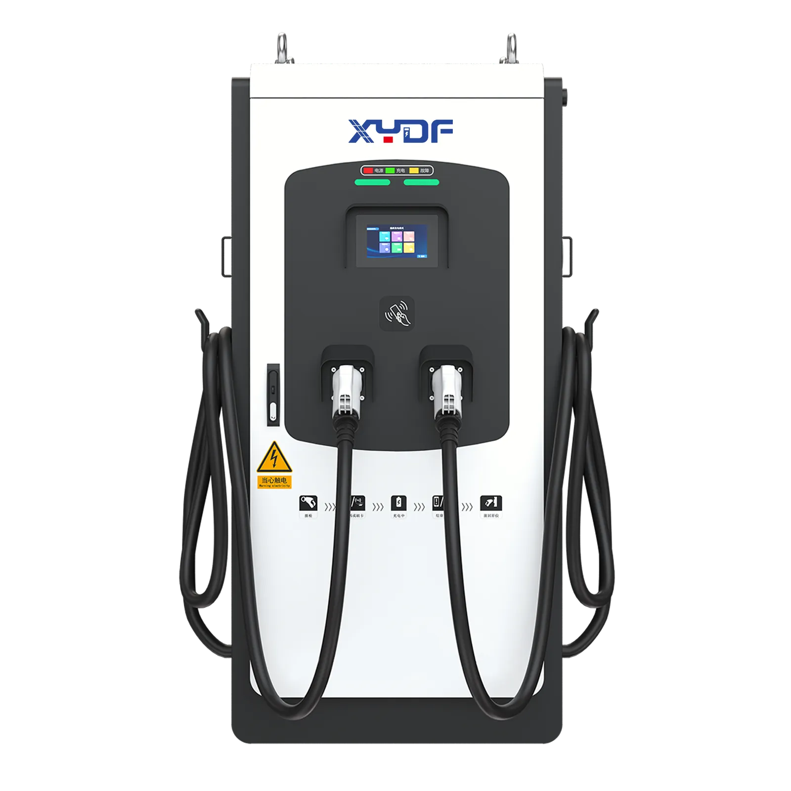
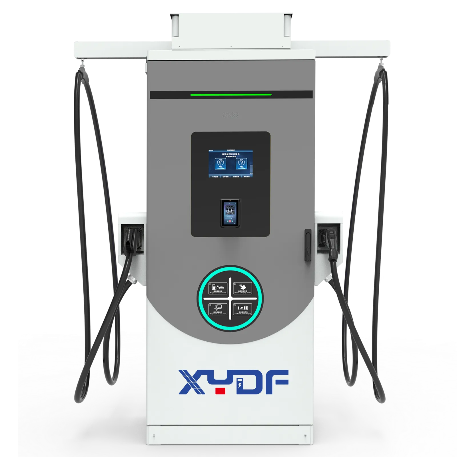
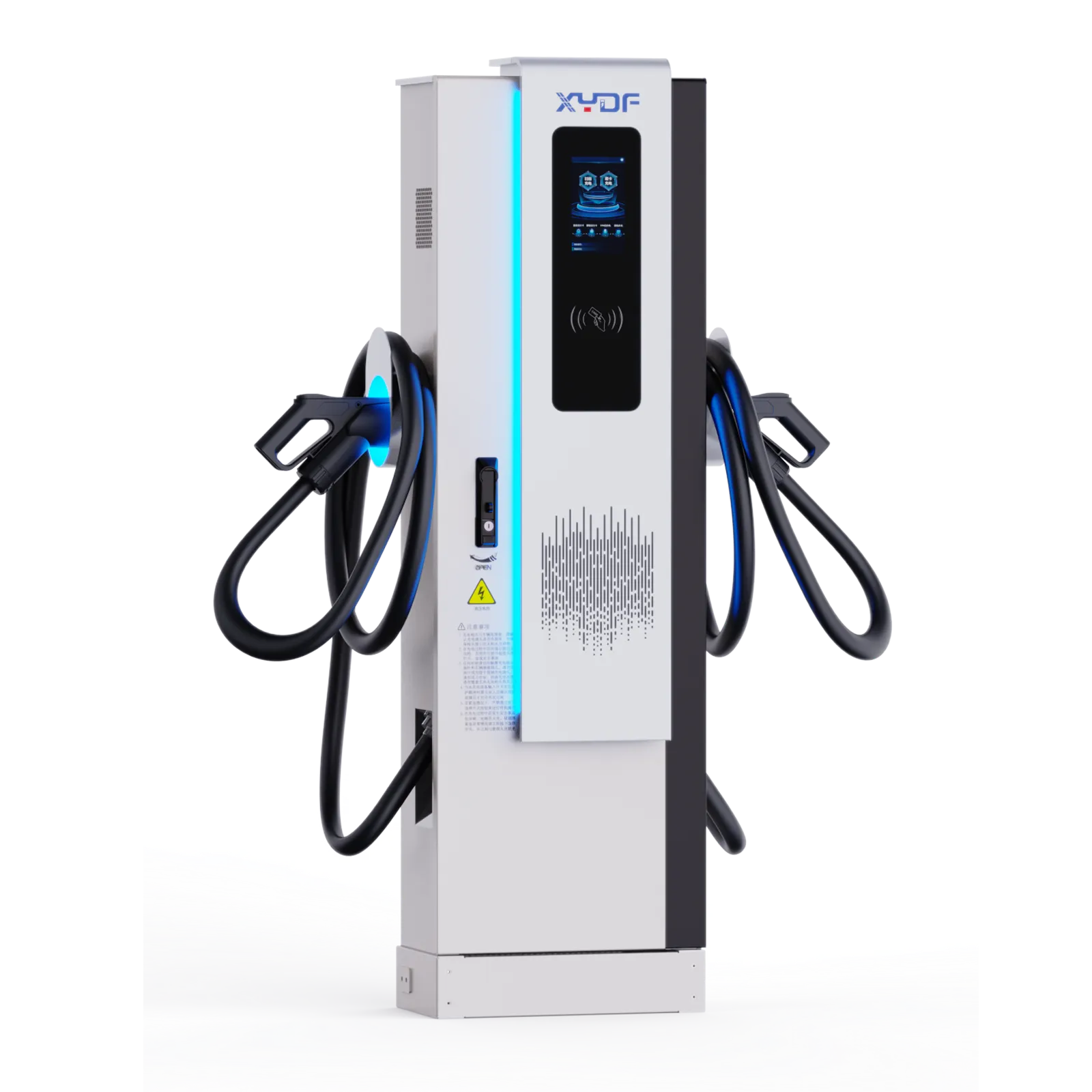
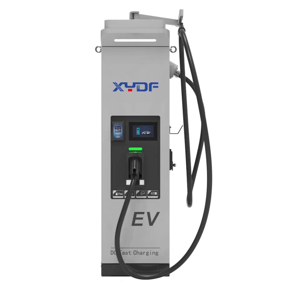
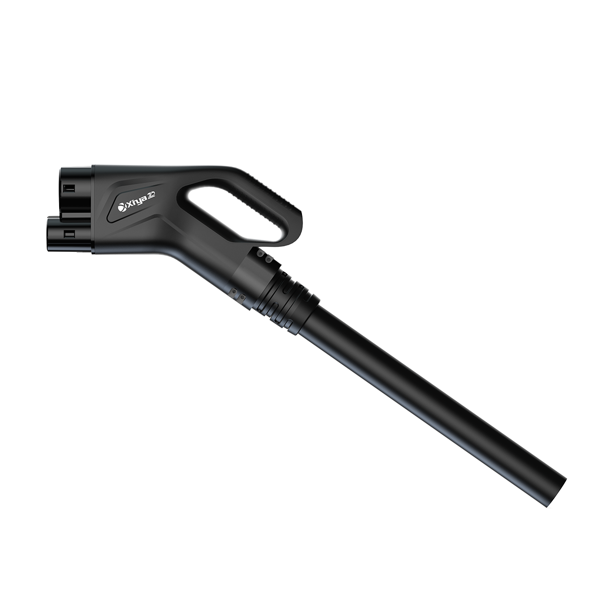
When an XYDF service engineer responded to a field-review note from Priya, a depot operations manager in Birmingham, six electric two-wheelers were waiting behind one three-wheeler with a nearly full battery. The team moved vehicles by hand, a charger connector was stretched across a loading lane, and the first delivery wave left late. This is an illustrative field-review scenario, not a named customer case or a claimed XYDF result: the visible failure looked like a bad charger, but a closer review pointed to a mismatch between vehicle acceptance, bay layout, and the shift schedule.
The lesson applies to many urban delivery hubs: a higher nameplate does not automatically remove a queue. Fleet managers need to size power, assign vehicles, and protect safe movement paths as one operating system.
Summary: For most E-2W and E-3W depots, a staged 30-60 kW design is more useful than choosing the biggest charger available. A 30 kW unit can suit predictable top-ups when vehicles accept that power, while 60 kW can shorten a peak turnaround only when the vehicle, connector, and site supply can use it. Start with a 15-minute arrival-and-departure log, then model simultaneous demand, charger sharing, and a physical cable route before procurement.
Electric two- and three-wheel delivery fleets have short routes but frequent stops, variable payloads, and hard dispatch cut-offs. The International Energy Agency (IEA) notes that electric mobility is expanding across multiple vehicle segments; depot planning therefore has to accommodate changing duty cycles rather than assume every vehicle behaves like a passenger car. Actual delivered power remains a function of vehicle acceptance, connector, charging protocol, grid capacity, and site design.
Match 30-60 kW to the delivery duty cycle
Power selection begins with energy required per shift. Record state of charge (SoC) on arrival, route distance, payload, ambient temperature, and the time available before the next dispatch. A simple illustrative calculation is useful: if a vehicle needs 18 kWh and can accept 30 kW for the relevant SoC window, the ideal energy-only time is about 36 minutes. Real sessions take longer because charging tapers, vehicles may not accept the full output, and staff need plug-in and release time.
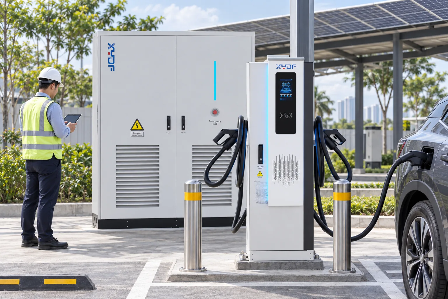
A 30kW EV charger can work well when most vehicles return in waves and have 45-90 minutes available during loading, sorting, or a driver break. It may be the better choice where the utility connection is constrained or where several lower-power connectors can serve more bays. A 60 kW cabinet is more compelling when a late return has less than 30 minutes before dispatch and the vehicle battery and connector are designed for that rate.
Do not read the kW label as a guaranteed charge rate. Battery management limits, temperature, SoC taper, connector rating, and simultaneous loads determine the session profile. Measure the site’s 15-minute demand interval and reserve capacity for refrigeration, conveyors, lighting, and other depot loads; a fast charger that trips the site’s peak limit is not a faster operating solution.
Compare power levels by queue outcome, not headline speed
The following comparison is directional. It describes planning tendencies, not guaranteed product performance or price.
A 50kW charging station is often considered a middle ground, but its value depends on whether the fleet can use that output during the useful part of each session and whether the site’s demand limit can absorb it.
| Configuration | Best-fit duty cycle | Queue and sharing effect | Key checks before approval |
|---|---|---|---|
| 30kW EV charger (single-output) | Predictable top-ups during loading or a long mid-shift pause | Lower instantaneous demand; one vehicle occupies the output longer | Vehicle acceptance, connector rating, arrival spread, utility headroom |
| 40kW EV charger (single-output) | Mixed routes with moderate turnaround pressure | Shorter sessions without assuming a full 60 kW connection | Whether the extra output is usable across the fleet’s SoC range |
| 50 kW charging station | Dense dispatch waves where a smaller number of bays must recover quickly | Can reduce dwell time, but may raise peak demand and demand charges | Load-management logic, service capacity, thermal derating, protection |
| 60 kW shared cabinet | High-priority turnaround and two vehicles sequenced through one power block | Power can be allocated between connectors; both vehicles may charge below 60 kW | Sharing algorithm, connector concurrency, vehicle limits, queue rules |
For a fleet with regular waves, compare the number of vehicles dispatched on time under each configuration. Include connection time, bay turnover, and the probability that two vehicles arrive together. A 40kW EV charger may outperform a nominally faster option if it allows more usable bays within the available electrical capacity.
Make multi-vehicle sharing work at the hub
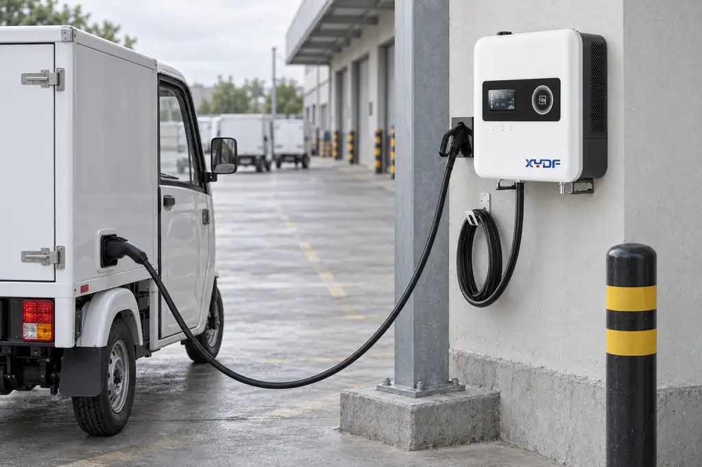
Charger sharing is an operations rule as much as a power-electronics feature. A shared 60 kW cabinet might give one vehicle priority, split power evenly, or reserve a minimum level for each connector. Ask suppliers to document the allocation logic, the trigger for priority changes, and what happens if one vehicle stops communicating.
Use the same data fields for every vehicle: arrival SoC, target departure SoC, estimated energy needed, departure deadline, and connector state. A fleet-control platform or a simple shift board can then rank sessions by dispatch time rather than by arrival order. Guidance on multi-connector DC charger power sharing is useful when evaluating whether a shared cabinet will actually reduce queues.
| Planning dimension | 30-40 kW approach | 50-60 kW shared approach | Operational question |
|---|---|---|---|
| Arrival pattern | Spread returns across loading windows | Absorb short, clustered return waves | How often do two or more vehicles arrive within 10 minutes? |
| Shift structure | Schedule routine top-ups before the next route | Protect a fast lane for urgent or late vehicles | Which departures have a fixed cut-off and which are flexible? |
| Grid constraint | Keep a larger margin for other depot loads | Use dynamic load management and documented demand limits | What import capacity remains after coincident building loads? |
| Bay count | More lower-power points may improve access | Fewer high-power points may simplify a compact site | Will drivers queue in a lane or circulate safely? |
Shift plans should include a recovery window. If a route returns late, the scheduler can move a flexible vehicle to a later slot while preserving the next dispatch. The practical objective of fleet EV charging is not maximum kW at every connector; it is enough usable energy at the right time with no unsafe vehicle movement.
Design for E-2W and E-3W safety and movement
Small vehicles create different hazards from passenger cars. Stands, kickstands, cargo boxes, and trailers can obscure a connector or create a trip point. Mark one-way circulation, keep cable loops off pedestrian paths, provide impact protection at equipment corners, and leave room to remove a vehicle without unplugging its neighbour.
For outdoor or semi-outdoor bays, specify weather protection and drainage appropriate to the enclosure and the local installation rules. Emergency isolation, residual-current protection, over-current protection, thermal monitoring, and clear status indicators should be defined in the electrical design and commissioning plan. The charging equipment should not be treated as a substitute for a site risk assessment or fire-safety procedure.
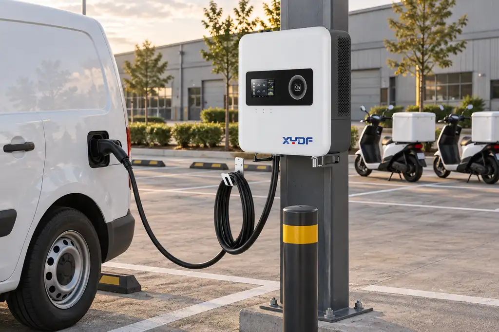
Review the loading sequence with drivers and maintenance staff. A commercial dc fast charger can be technically suitable yet operationally poor if its cable cannot reach the inlet from the assigned parking orientation. The guidance on commercial EV charging parking layout and cable routing helps teams test the physical arrangement before concrete and conduit are installed.
Standards, compliance, evidence, and procurement
IEC 61851-1 describes general conductive charging-system requirements; it is a technical standard, not a blanket approval for every installation. Connector and communication choices may bring in additional IEC or regional requirements, and the applicable electrical, building, accessibility, and fire rules depend on the destination market and site classification. ISO 15118 addresses vehicle-to-grid communication functions for supported implementations; it does not guarantee that every E-2W or E-3W will use those functions.
Ask for a declaration of applicable standards, installation instructions, protection settings, environmental ratings, and commissioning test records. Confirm who is responsible for the upstream switchgear, earthing, protection coordination, network security, and maintenance. Marketing a unit as “fast” or “safe” without defining the test method, vehicle conditions, and installation boundary can create procurement disputes and regulatory exposure.
For demand planning, compare the charger profile with the site’s utility tariff and peak-demand rules. The practical controls described in commercial EV charging peak-demand cost control can be evaluated alongside route and dispatch data, not as a separate finance exercise.
- Build a route-and-SoC baseline. Capture at least two weeks of arrivals, energy needed, connector type, and dispatch deadlines; label missing data rather than filling it with averages.
- Model simultaneous demand. Test normal, late-return, cold-weather, and maintenance scenarios, including non-charging depot loads and the utility’s demand limit.
- Specify the sharing rule. State whether the system prioritises deadline, minimum SoC, first-in order, or an operator override, and require an event log for troubleshooting.
- Walk the layout at vehicle scale. Use the actual E-2W and E-3W dimensions, cargo attachments, turning paths, protective barriers, and emergency access; a scaled drawing alone can miss cable reach problems.
- Request an evidence pack. Include datasheets, applicable standard declarations, protection and isolation details, software update policy, warranty boundaries, spare-parts route, and commissioning responsibilities.
XYDF can be considered as one source for configurable commercial charging equipment and documentation, subject to matching the selected configuration with the vehicle, connector, grid study, and local installation requirements. Procurement teams should compare evidence and service scope across qualified suppliers rather than select on a power label alone. For context on turnaround planning, see this fleet charging turnaround-time framework.
Frequently asked questions
What charger power is best for e-2W and e-3W delivery fleets?
There is no universal best rating. Choose the lowest output that reliably restores the required energy before the next dispatch while allowing for tapering, late arrivals, and other site loads. Vehicle acceptance, battery size, connector, grid capacity, and the hub’s queue rule should be documented before selecting a commercial dc fast charger in the 30, 40, 50, or 60 kW range.
Is 30 kW or 60 kW charging better for delivery turnaround time?
60 kW can reduce energy dwell when the vehicle and site can use it, but it may not improve turnaround if the charger is shared, the battery tapers, or vehicles already have a long loading window. 30 kW can provide a more predictable and lower-peak solution for scheduled top-ups. Compare on-time departures in a duty-cycle model rather than on nominal output.
How many vehicles can share one DC charger at a delivery hub?
The answer depends on the number of connectors, the cabinet’s sharing logic, and the energy each vehicle needs. Two vehicles might share a 60 kW block, but each could receive less than 30 kW during overlap; a supplier should provide the allocation curve and connector-concurrency limits. Queue design and deadlines matter as much as the connector count.
Can delivery fleets charge during loading and dispatch?
Yes, if charging bays are placed outside the active loading path and the cable can reach the inlet without crossing pedestrian or vehicle lanes. Assign a charging state in the loading checklist, and prevent dispatch until the connector is released and the bay is clear. A site risk assessment should define separation, isolation, and emergency access.
How should a hub schedule charging across multiple delivery shifts?
Rank sessions by departure deadline, energy required, and vehicle priority, then reserve capacity for late returns and essential building loads. Publish a repeatable handover between shifts so a partially charged vehicle is not treated as available by mistake. Recalculate the plan when route length, payload, weather, or fleet size changes.
What safety features are important for e-2W and e-3W charging hubs?
Specify correctly rated connectors and cables, residual-current and over-current protection, emergency isolation, thermal and fault monitoring, impact protection, weather-appropriate enclosures, and clear status indications. Pair those features with marked bays, cable management, inspection routines, and trained operators. Confirm the exact requirements with the local electrical and fire authorities.
References
- International Energy Agency, Global EV Outlook 2024.
- U.S. Department of Energy Alternative Fuels Data Center, Electricity Infrastructure Trends.
- IEC 61851-1, Electric vehicle conductive charging system — General requirements.
- ISO 15118-1, Road vehicles — Vehicle to grid communication interface.
The fastest depot is the one that delivers the right energy to the right vehicle before its deadline, with every movement and electrical limit accounted for.
When your team is ready to compare a 30-60 kW concept with site constraints, review the commercial EV charging station range and contact XYDF with your vehicle list, shift pattern, connector plan, and available grid capacity. This is the practical measure of fleet EV charging performance.