 Xinya Dongfang Electricity Technology Co., Ltd.


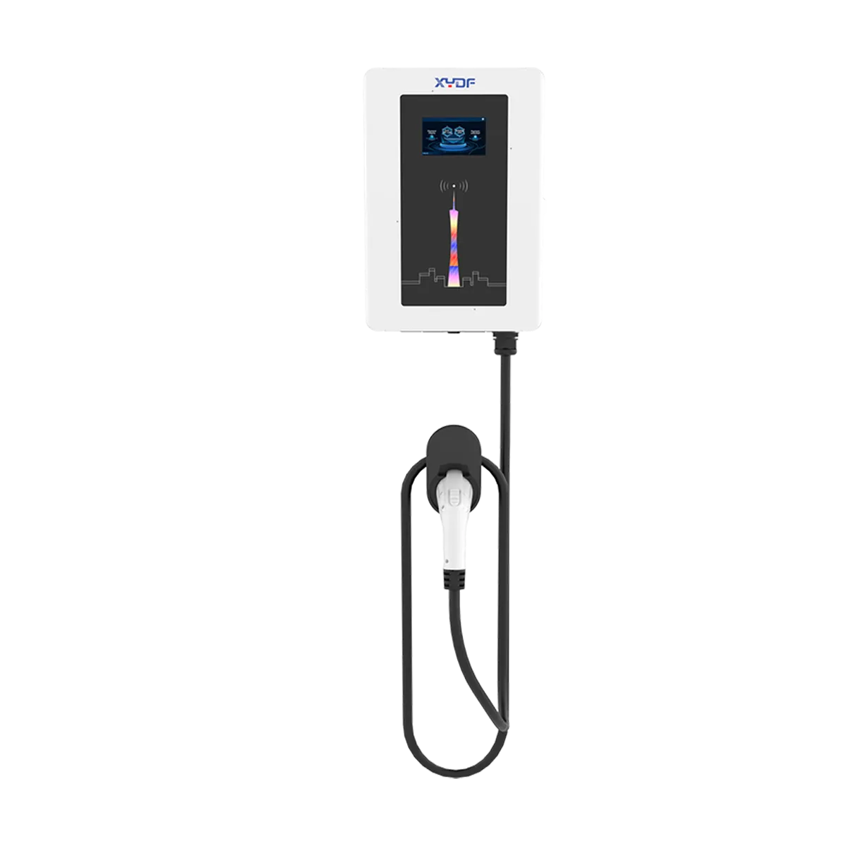
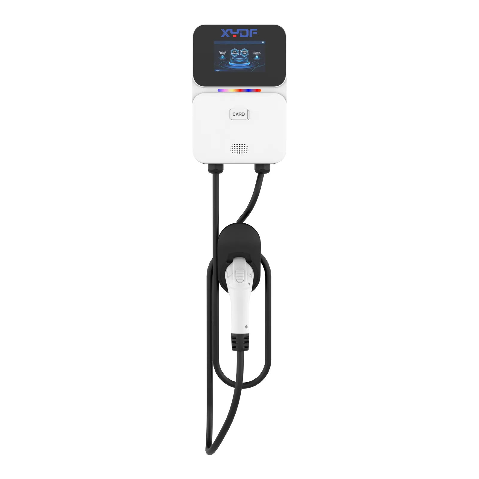
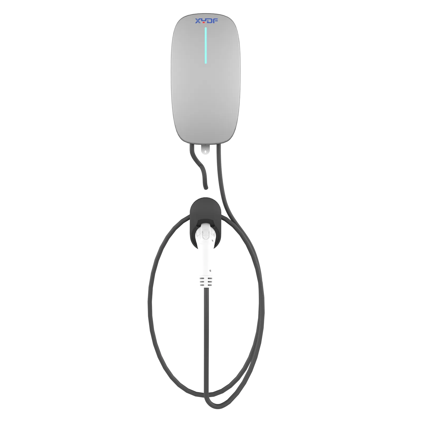
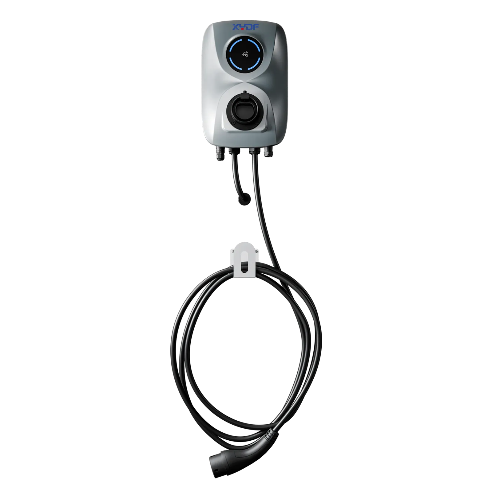
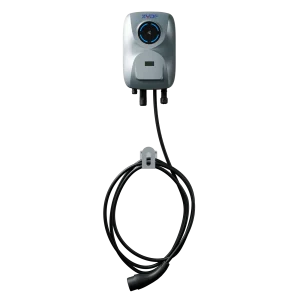
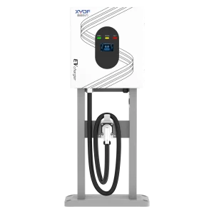

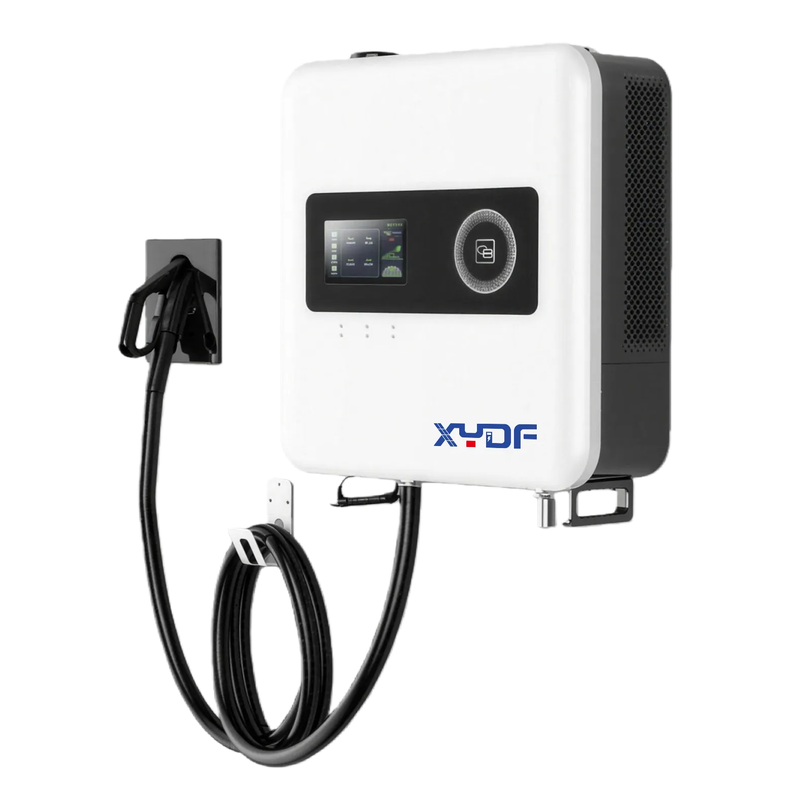
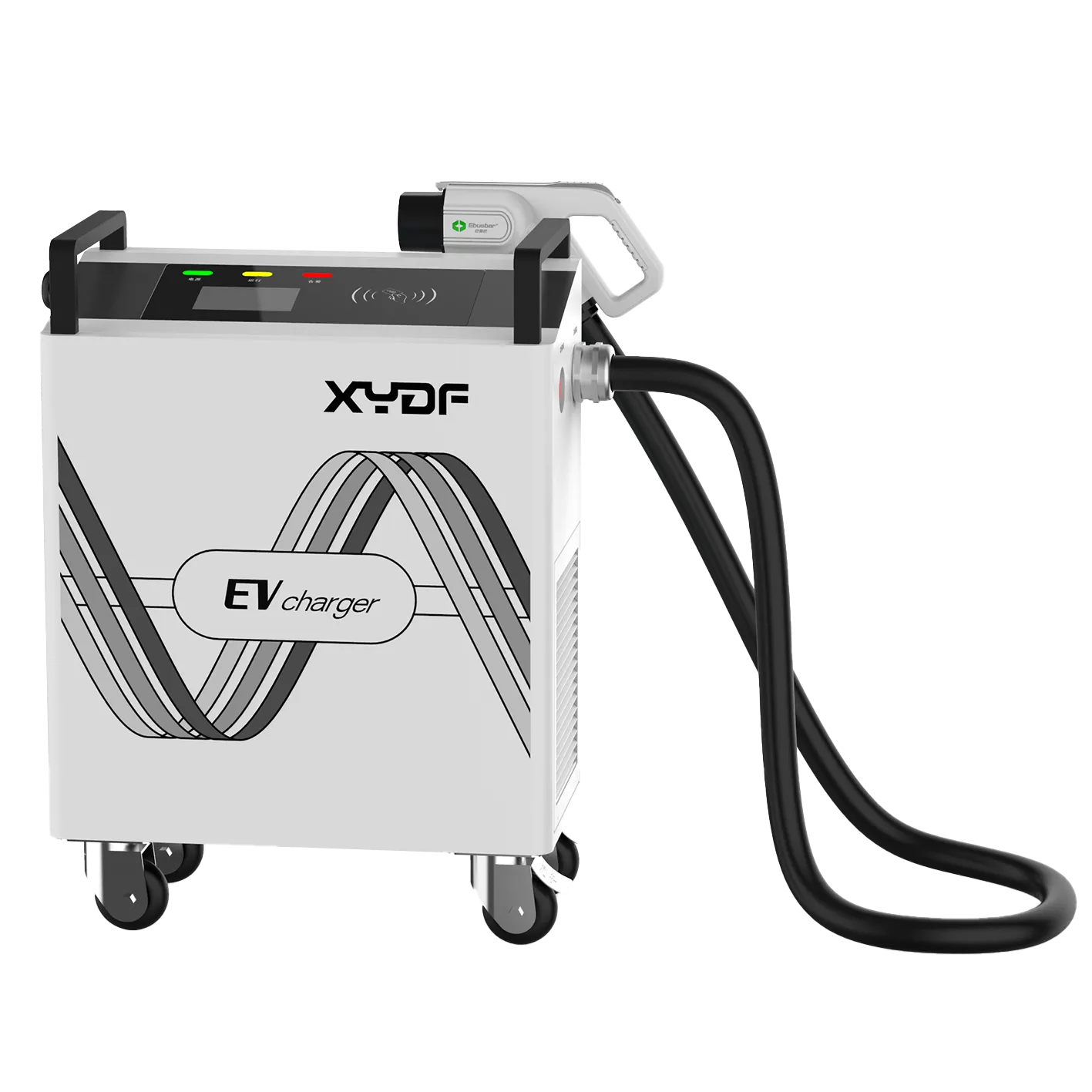
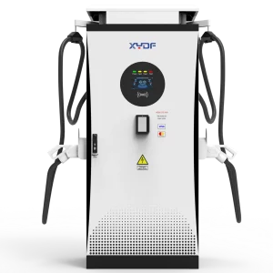
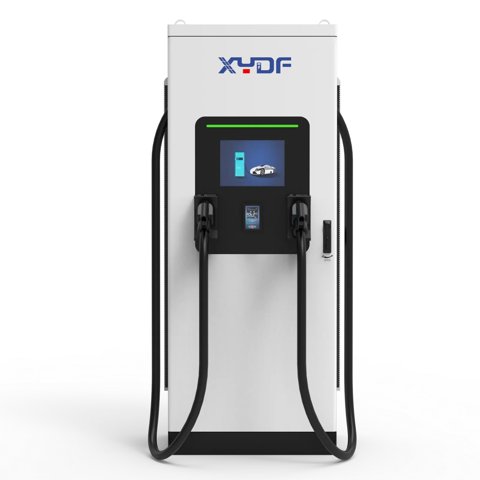
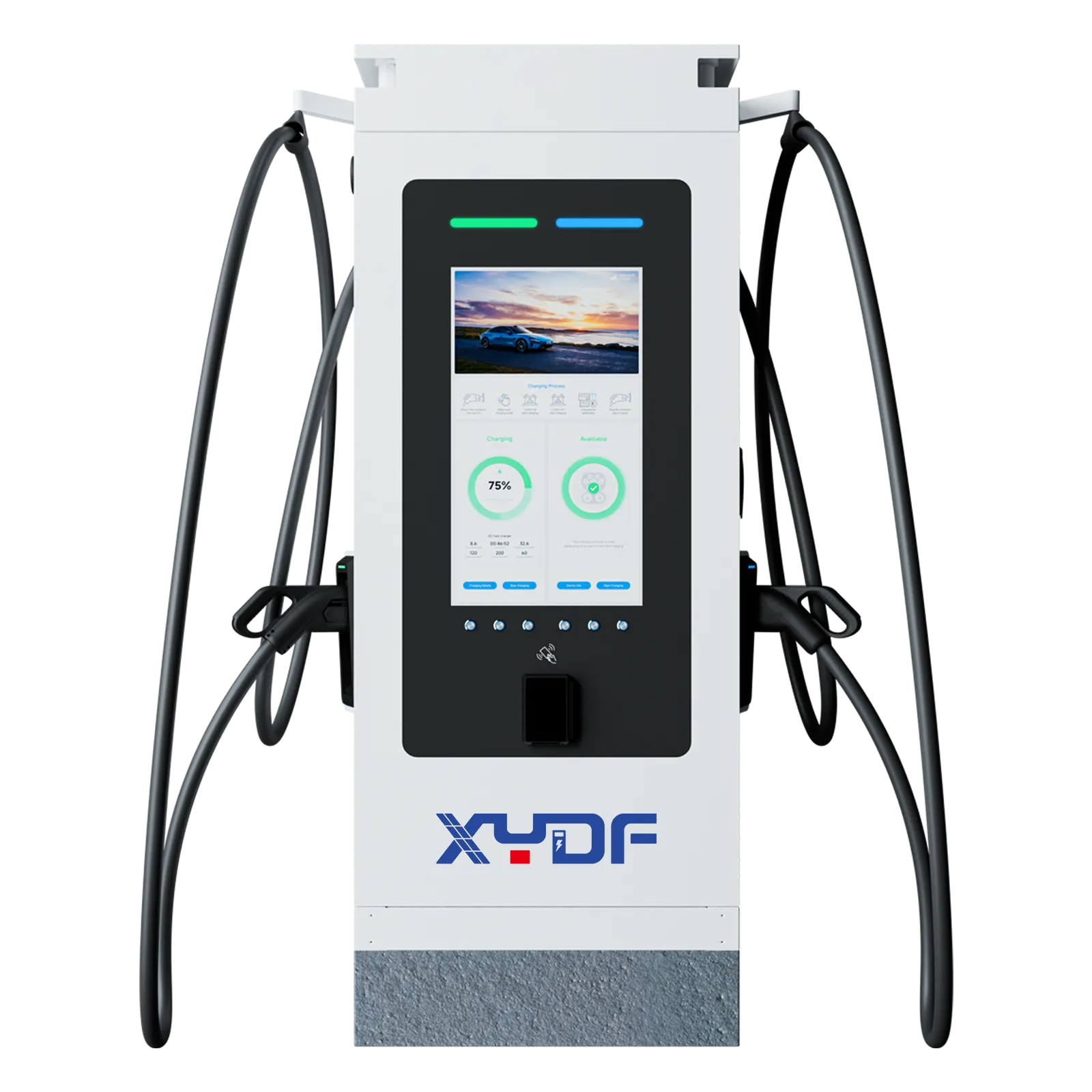
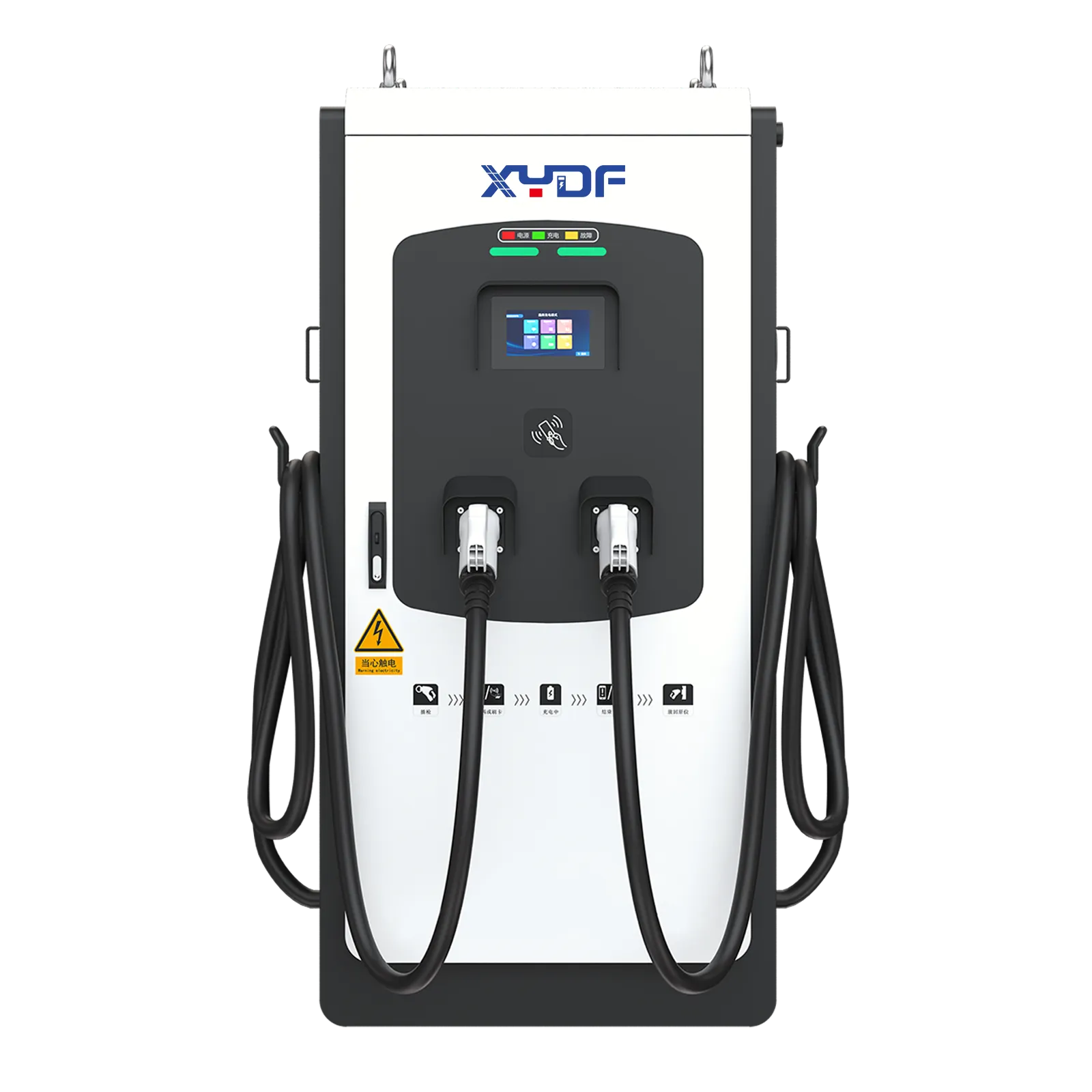
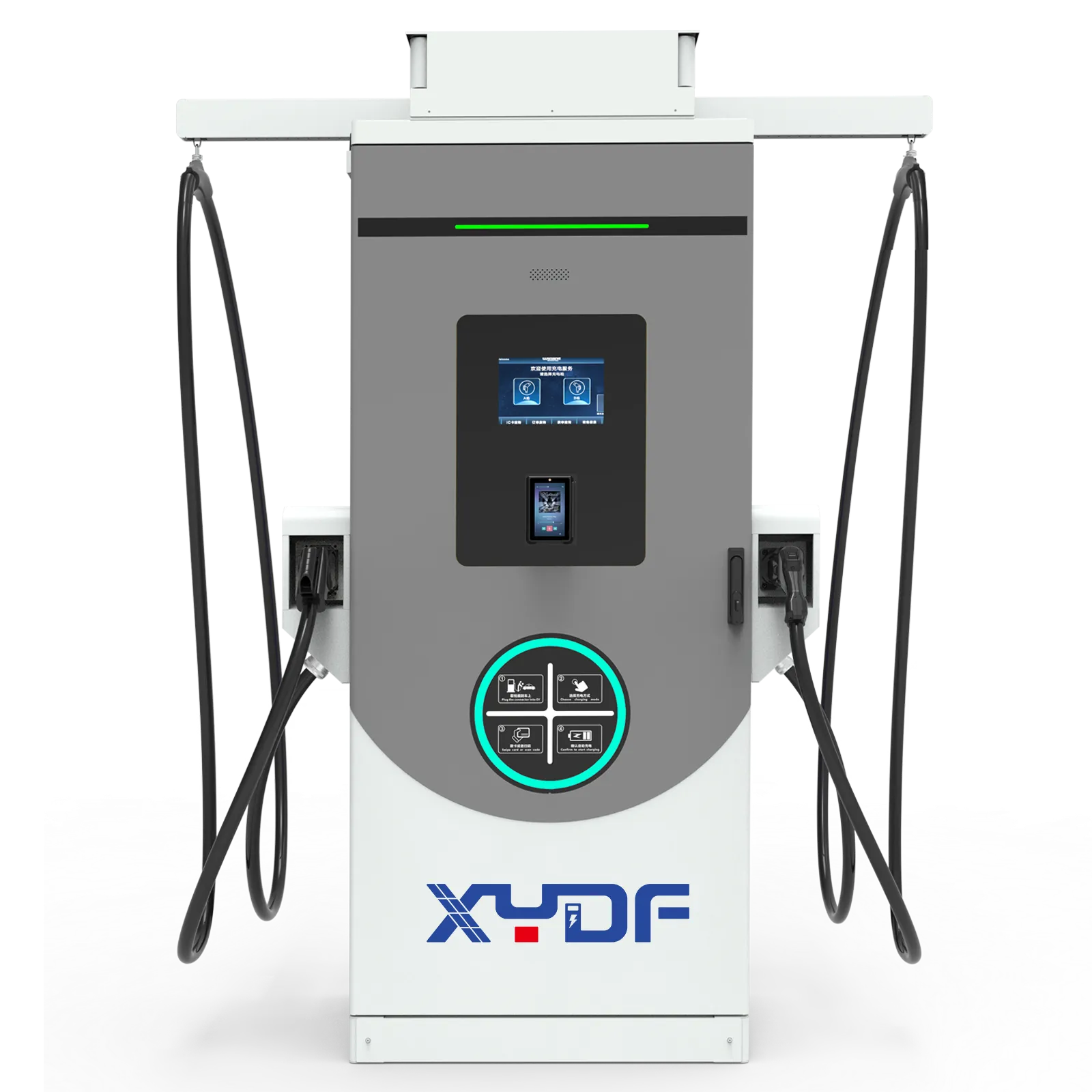
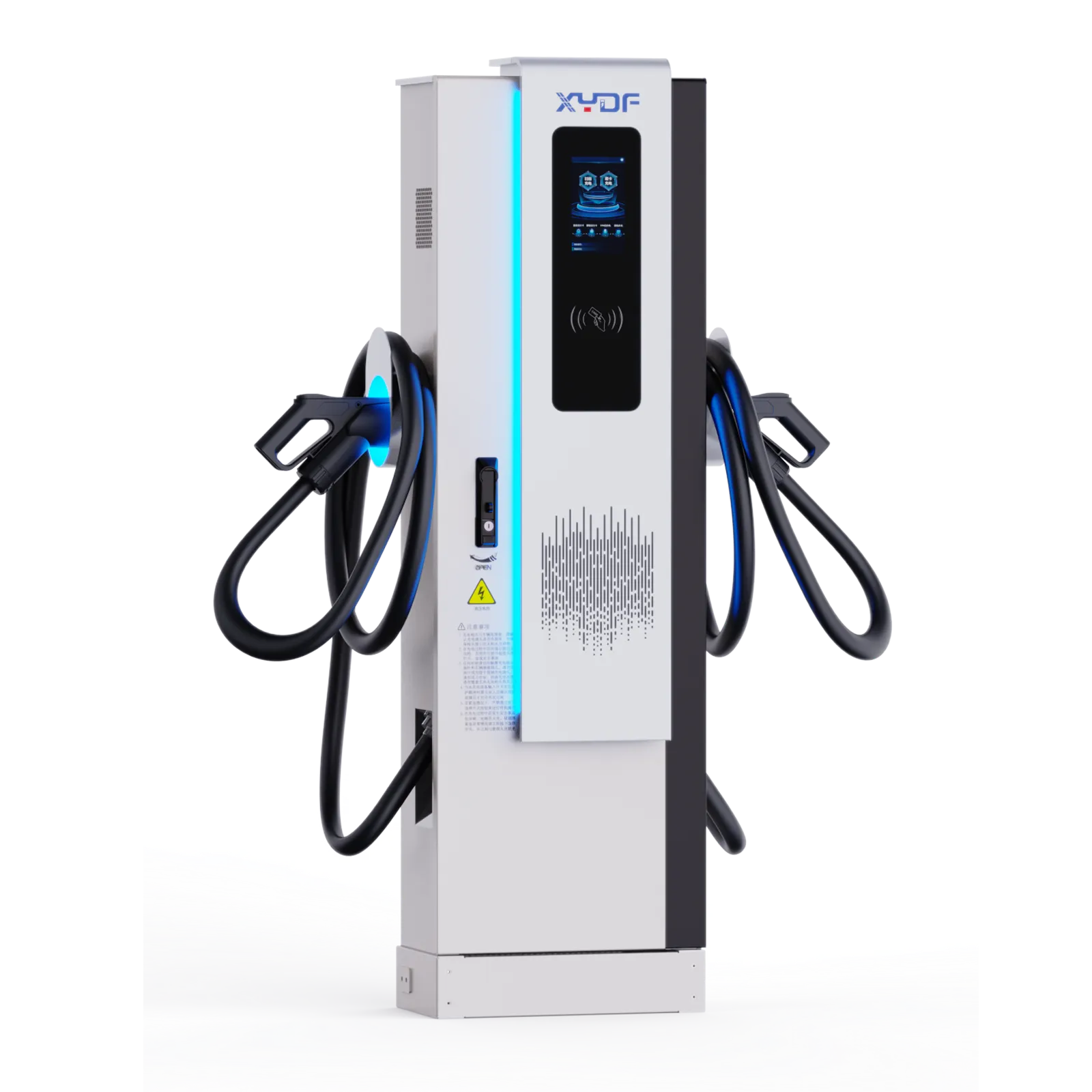
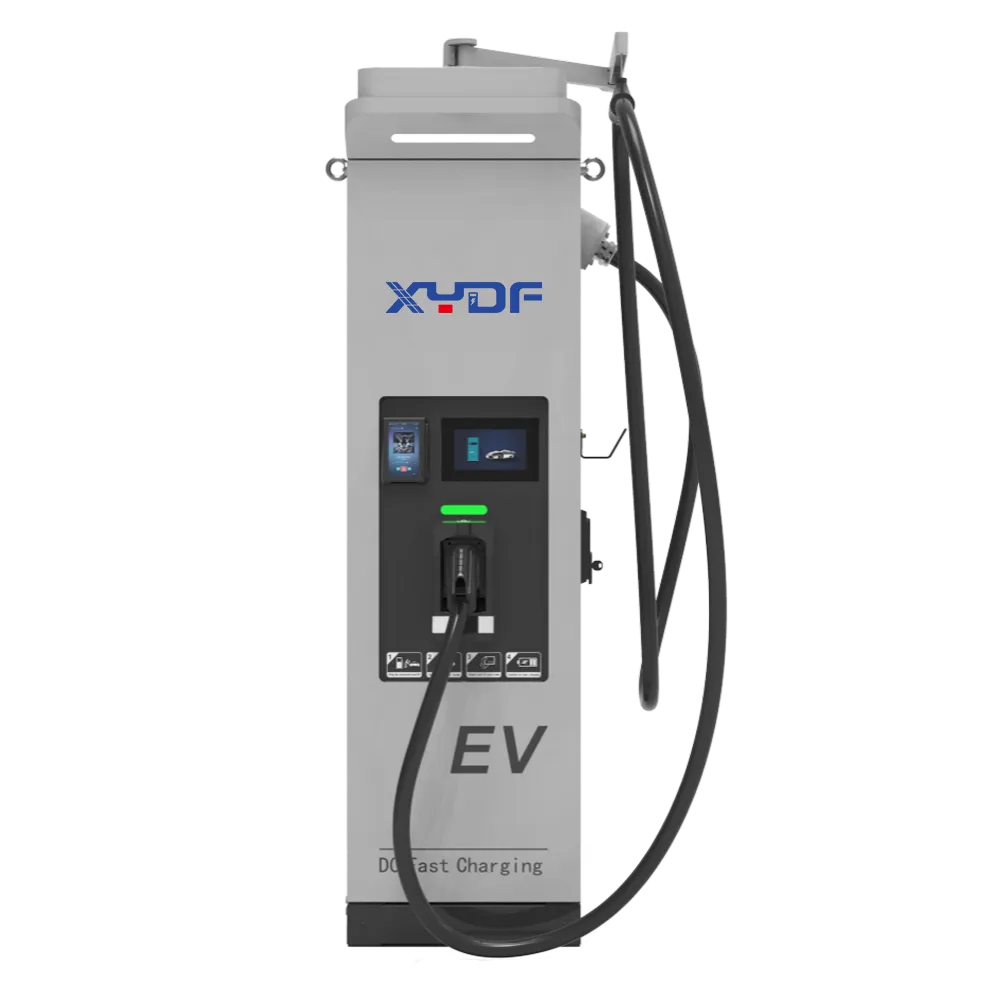
When Elena, an EPC electrical lead in Rotterdam, was asked to energize six new taxi bays before winter, she approved six 350 kW dispensers and ordered a 2 MVA transformer. On commissioning day, the utility limited the site to 1.25 MVA, two cars repeatedly reduced power, and the protection relay opened during a simultaneous departure rush. Her team changed the operating envelope, not the charger brand: they modelled vehicle voltage, dwell time and a shared power ceiling, then re-sized the transformer and software schedule. The revised site served more vehicles with less peak demand. The failure was a selection and power-planning error, not evidence that the original hardware was “bad.”
Summary: To understand how to choose a dc fast charger, begin with a 15-minute load profile, vehicle voltage mix and grid limit—not a headline kW number. A 400 V car, an 800 V car and a 200 kW vehicle can all receive different power from the same cabinet because of current limits and the charging curve. We recommend specifying an IEC 61851-1-compliant system, validating connector and communications interoperability, and comparing five-year total cost of ownership (TCO), including demand charges and service access. The practical sequence is: define use cases, reserve electrical capacity, select architecture and cooling, test software and safety, and write measurable acceptance criteria.
This guide is for EPCs, charging-point operators (CPOs), fleet and depot owners, site developers and technical procurement teams. It treats a DC charger as one part of an energy system: utility connection, transformer, switchgear, cable routing, vehicle interface, payment or authorization, monitoring and maintenance all influence the result. The International Energy Agency’s Global EV Outlook documents continued growth in electric-car sales and public charging, but growth does not make every high-power site economical. Right-sizing is a design discipline.
1. Start with the duty cycle, not the catalogue
Write a one-page duty-cycle brief before comparing suppliers. State the vehicle classes (cars, vans, buses, trucks), battery sizes, arrival state of charge (SoC), target departure SoC, dwell time, number of bays, weather range and operating hours. Distinguish a highway stop, where a driver may wait 15–30 minutes, from a depot, where vehicles can charge for six hours overnight. A 60 kW unit may be the right answer for a delivery fleet with long dwell; 480 kW may be justified for a coach terminal with short turns.
Use measured or defensible assumptions. An illustrative calculation: a 75 kWh battery arriving at 20% SoC needs about 60 kWh to reach 100% before losses. If the vehicle is parked for 60 minutes, an average of roughly 60–70 kW at the battery (allowing conversion losses) may suffice; a 350 kW nameplate will not reduce the last minutes of taper. Label such numbers as illustrative, and replace them with fleet telematics or a monitored pilot.
Separate energy need from throughput. Energy per day (kWh) drives utility consumption and renewable-storage sizing; simultaneous sessions and their overlap drive transformer and demand-charge exposure. A simple spreadsheet with 5-minute intervals should include charger efficiency, auxiliary loads, battery SoC limits and a conservative diversity factor. Test a “worst credible” event: all bays arrive within 10 minutes after a shift, ambient temperature is at the design extreme, and one power module is unavailable.
Power selection by application
| DC output class | Typical application | Traffic and energy need | Planning note |
|---|---|---|---|
| 30 kW | Workplace, hotel, small commercial parking | Low traffic; 20–60 kWh sessions with 1–4 hour dwell | Often fits a modest service upgrade; confirm cable length and accessibility. |
| 60 kW | Urban fleet, retail, taxi overflow | Moderate traffic; 40–100 kWh sessions with 45–120 minute dwell | Good balance where vehicles turn over steadily rather than all at once. |
| 120 kW | Public forecourt, delivery depot, regional hub | Medium-high traffic; 60–150 kWh sessions with 30–90 minute dwell | Check whether two connectors share a 120 kW cabinet or each receives dedicated power. |
| 240 kW | Highway site, bus layover, logistics yard | High traffic; 100–250 kWh sessions with 20–60 minute dwell | Transformer, harmonic study and cable thermal design become central. |
| 480 kW | Truck corridor, coach terminal, premium highway hub | Very high traffic; 200–600 kWh sessions with 15–45 minute dwell | Usually needs liquid-cooled cables and a carefully staged grid connection. |
| 960 kW | Megawatt-ready logistics or multi-dispenser plaza | Exceptional throughput; several hundred kWh per turn with overlapping departures | Specify power sharing, protection coordination, civil works and utility constraints early. |
These bands are starting points, not performance promises. Confirm the vehicle’s maximum DC current, pack voltage and battery thermal state. A charger advertised at 240 kW may deliver less when a 400 V vehicle reaches its current ceiling; an 800 V vehicle may use the same cabinet more effectively. The article EV Fast Charging Curves Explained is useful when explaining this distinction to non-specialist stakeholders.
2. Match voltage, current and the charging curve
Power is voltage multiplied by current. Many passenger EVs operate around 350–500 V, while newer platforms use 700–900 V. If a cabinet is limited to 500 A, a 400 V vehicle may receive about 200 kW and an 800 V vehicle about 400 kW, subject to the vehicle, cable and charger limits. The figures are illustrative; procurement documents must state guaranteed operating ranges and test conditions. That is why how to choose a dc fast charger is fundamentally a voltage-and-current question, not a badge on the enclosure.
Charging is not a flat line. The battery management system requests current, holds a high-power window, then tapers as SoC and cell voltage rise. Temperature, battery pre-conditioning, pack age and state of health alter the curve. Compare time-to-energy at a defined SoC window (for example, 10–80%) rather than quoting “peak kW.” Require a supplier to provide a trace from a repeatable test protocol, with ambient temperature, cable length and vehicle model recorded.
400 V versus 800 V site implications
400 V vehicles remain a large installed base, so a site serving mixed fleets should not optimize only for 800 V. High current on a 400 V session raises conductor heating, voltage drop and connector ergonomics; cable cooling and routing need attention. 800 V vehicles can transfer the same energy with roughly half the current, potentially reducing losses, but only if the vehicle and charger negotiate that voltage. The companion guide 400V vs 800V Vehicles: How Should a Site Select DC Chargers? outlines a mixed-voltage decision process.
Specify a wide DC voltage window, current limits at both ends, isolation monitoring and controlled contactor sequencing. Ask how the system behaves when a vehicle requests a voltage outside the cabinet’s range: it should reject safely and report a clear fault, not repeatedly reset. For buses and trucks, record auxiliary loads and pantograph or liquid-cooled connector options separately from passenger-car CCS or NACS requirements. In other words, how to choose a dc fast charger should be answered with a testable operating envelope for every vehicle class.
Power sharing and queuing
A multi-connector cabinet may have 240 kW available while two cars are connected. Software can allocate 180/60 kW, 120/120 kW, or a dynamic split based on SoC and departure priority. Define the policy in the functional specification: equal share, first-in-first-served, minimum guaranteed power, or fleet-priority queuing. Include a fallback when communications fail. The guide How Does Power Sharing Work in a Multi-Connector DC Charger? provides terminology for that workshop and clarifies EV charger power sharing as an operational control.
Power sharing is also a grid-control tool. A site energy-management system (EMS) can cap aggregate import, respond to a utility signal, or coordinate on-site solar and storage. Require logs showing requested, delivered and curtailed power per session. This makes billing, customer support and demand-charge review auditable.
3. Engineer the electrical backbone
Utility capacity is often the binding constraint. A 960 kW charger does not necessarily require a 960 kW transformer if an EMS enforces a lower import cap, but the cap must align with service rules and operating commitments. Account for transformer nameplate, power factor, efficiency, switchgear continuous ratings, cable derating, harmonic current and future expansion. This is the core of DC charging power planning. The detailed Transformer Capacity Planning for DC Fast Charging Sites article can support an early utility conversation.
Use a load-flow and short-circuit study with the actual charger topology. Rectifiers can introduce harmonics; ask for conducted-emission data and mitigation options, then verify at site acceptance. Protection coordination should cover upstream breakers, charger input protection, DC output contactors and residual-current monitoring. Earthing and equipotential bonding must follow local electrical code; IEC 62477-1 provides a safety framework for power electronic converter systems, but local rules still govern the installation.
Demand charges can dominate operating cost even when energy prices are moderate. An illustrative example: if a tariff applies a monthly demand charge to the highest 15-minute import and an unmanaged site peaks at 800 kW, reducing the peak to 500 kW may matter more than a small efficiency difference. Do not convert this illustration into a savings guarantee; obtain the tariff sheet, interval data and utility-approved control limits.
Plan civil works for the full life cycle. Reserve ducts and breaker space for an additional cabinet, provide drainage and bollards, and leave safe clearances around service doors. Locate transformers and switchboards to minimize voltage drop while keeping noise, fire separation and public access in mind. A neat single-line diagram, cable schedule and as-built model often save more time than a marginally higher peak rating.
Modular and split architectures
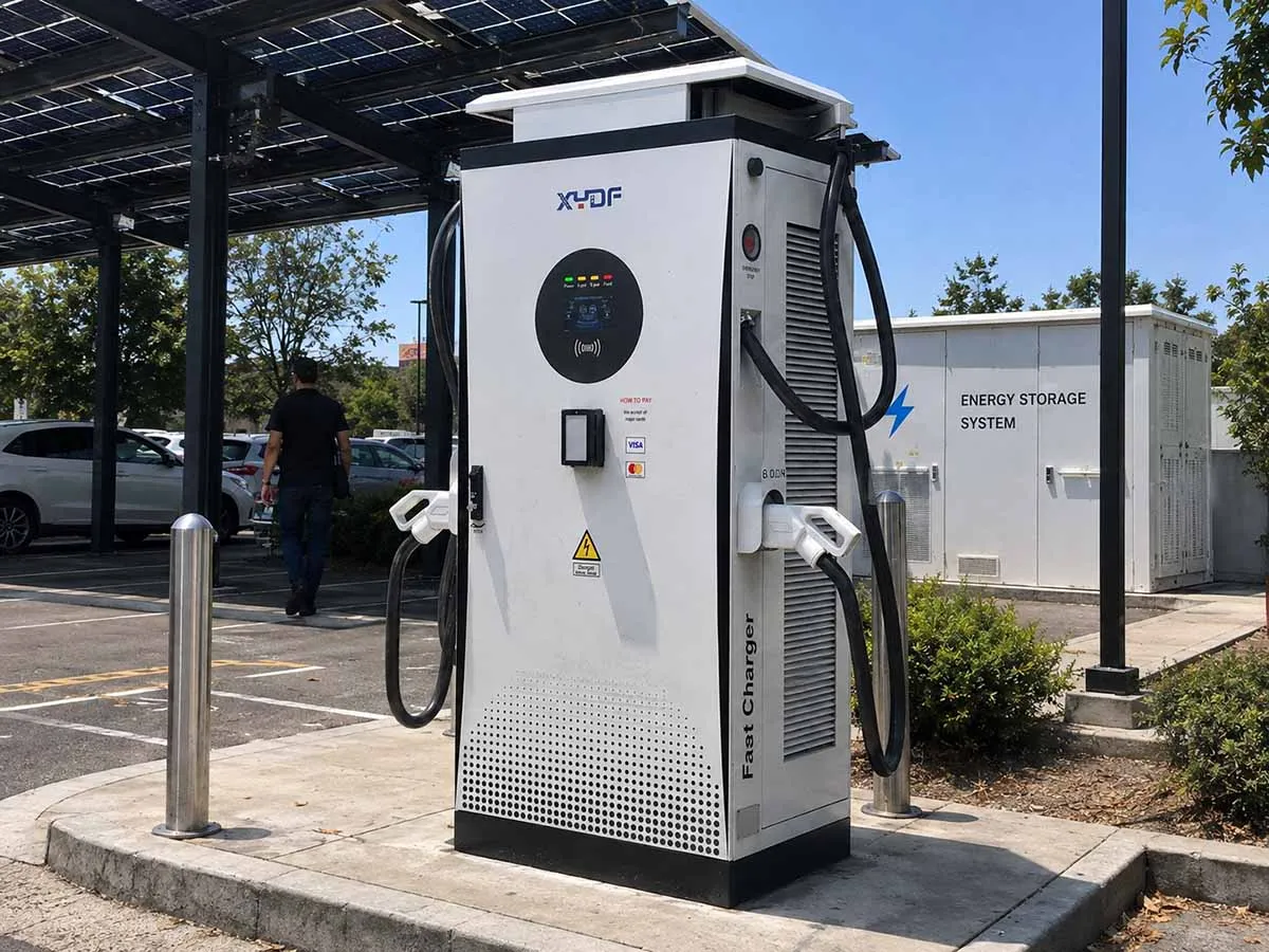
In an all-in-one charger, power electronics and dispenser sit in one enclosure. Installation can be faster for a small site, but the footprint and service access may be less flexible. A split system places power cabinets away from dispensers, allowing a compact parking island and shared modules across several stalls. Compare feeder length, thermal environment, cable cost, accessibility and expansion path. See All in One vs Split EV Charging Solution for a neutral checklist.
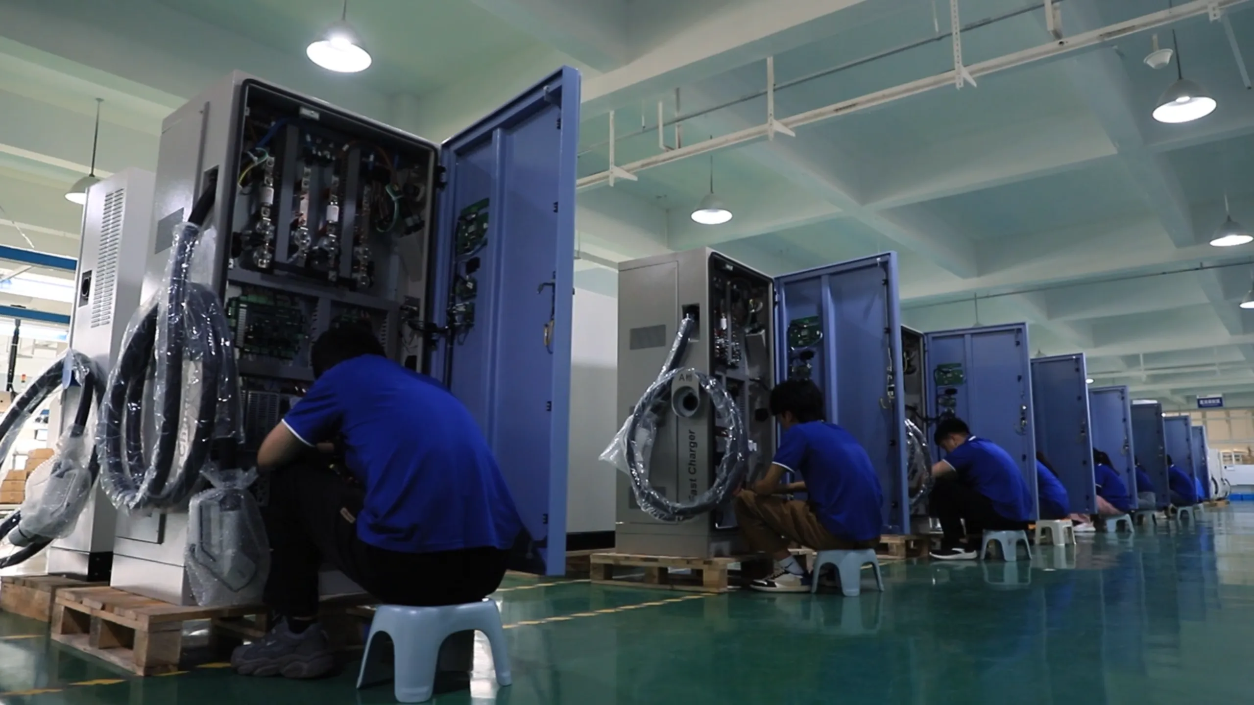
Modularity affects uptime. If a 60 kW module fails in a 240 kW cabinet, a derated 180 kW service may continue while a technician replaces the module. Ask for hot-swap boundaries, mean time to repair assumptions, spare-part lead times and a safe isolation procedure. The article Modular DC Fast Chargers: Capacity Expansion, Repair, and Downtime explains how to turn those questions into contract requirements.
4. Choose cooling, connectors and maintainability together
Air cooling can be appropriate for lower power or moderate ambient conditions, with simpler service routines and fewer fluid components. Liquid cooling supports high-current cables and compact power density, but adds pumps, heat exchangers, coolant quality checks and leak detection. Compare sound levels, filter replacement, derating curves and environmental ratings, not just the cooling label. The maintenance checklist for liquid-cooled DC fast chargers is a practical starting point.
Specify operating temperatures, humidity, altitude, salt mist, dust and flood exposure for the actual site. Require thermal alarms that distinguish a sensor fault from genuine over-temperature, and define a controlled power reduction before shutdown. A clear derating curve is more useful than an unexplained “full power in all weather” statement.
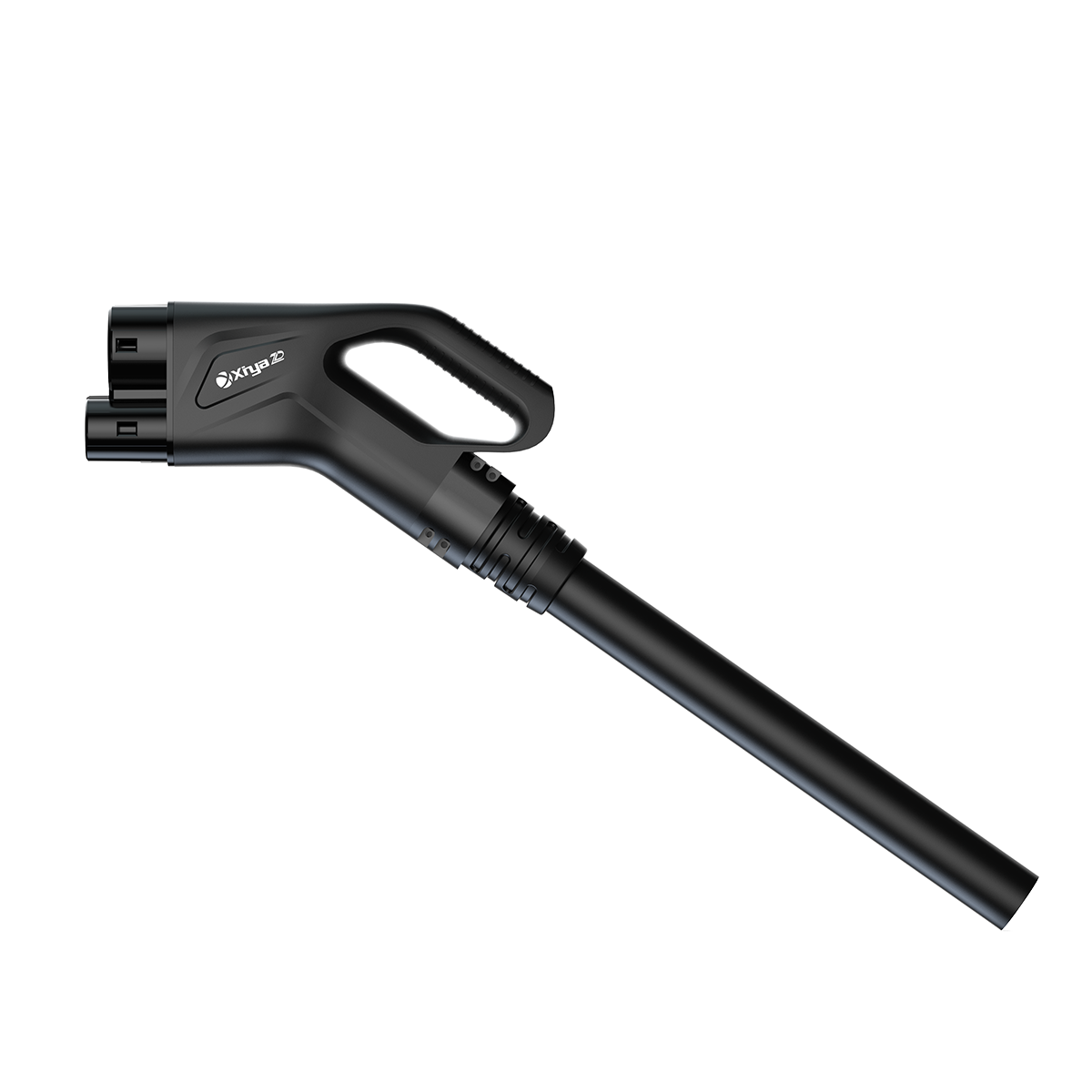
Connector compatibility is a system issue. In Europe, CCS2 is common; North American deployments may require CCS1, NACS or adapters; CHAdeMO remains relevant in some installed fleets; buses and trucks may use higher-power liquid-cooled connectors. Verify electrical pinout, locking, cable reach, payment workflow and vehicle communication. ISO 15118 features such as Plug & Charge are optional capabilities that depend on vehicle, certificate and backend support. The DC Fast Charger Compatibility Guide for Operators helps map those dependencies.
Write maintainability into the layout: front or rear service access, lockout/tagout points, replaceable fans or pumps, remote diagnostics, event-log export and firmware rollback. Define uptime as a measurable service-level metric—such as availability by connector and by month—with exclusions for utility outages, vandalism and planned maintenance agreed in advance. Ask how the supplier proves availability and how incidents are escalated; do not accept an undefined “99.9%” headline.
5. Compare options on value, not peak power
The table below is a procurement lens. “Unit-cost tendency” is qualitative because civil works, utility tariffs, quantities and geography vary; no project price should be inferred. Efficiency should be tested at representative loads, not only at a laboratory sweet spot.
| Dimension | Lower-power air-cooled all-in-one | High-power liquid-cooled or split system | Questions for the tender |
|---|---|---|---|
| Performance | Best for longer dwell and predictable sessions | Best for short dwell and high throughput | What energy is delivered in 10–80% tests for each target vehicle? |
| Efficiency | Often efficient at moderate load; verify standby draw | May add pump and fan loads; can reduce cable losses at high current | Provide weighted efficiency and auxiliary consumption by load point. |
| Durability | Fewer fluid components; filters still need care | More thermal components; robust if coolant monitoring is designed well | Which parts are consumables, and what environmental tests were run? |
| Compatibility | Usually a narrower power and connector envelope | Can support multiple dispensers and voltage classes | List supported protocols, connectors and vehicle test evidence. |
| Installation | Compact scope for small service upgrades | Requires coordinated transformer, ducts and communication paths | Return a single-line diagram, heat rejection and civil interface schedule. |
| Unit-cost tendency | Lower equipment complexity; site cost can still dominate | Higher equipment complexity; shared cabinets may reduce cost per stall | Provide a transparent bill of materials and excluded works. |
| Maintenance | Filter, fan and connector inspection are familiar tasks | Module, pump, coolant and leak-detection procedures are important | State MTTR assumptions, spares, training and remote support hours. |
| Returns and TCO | Can maximize utilization where dwell is long | Can maximize revenue per bay where demand is high | Model utilization, demand charges, downtime and expansion over five years. |
Dimension table: match the site’s dominant constraint
| Dominant constraint | Design response | Evidence to request |
|---|---|---|
| Limited grid import | EMS cap, staged charging, storage or a service upgrade | 15-minute simulation, fail-safe behavior and utility approval path |
| Short vehicle dwell | Higher current, liquid-cooled cable and queue-aware sharing | Vehicle test traces, cable temperature and connector ergonomics |
| Mixed 400/800 V fleet | Wide voltage window and explicit current limits | Independent test reports for representative vehicles |
| Harsh climate | Appropriate IP/IK, corrosion protection and derating margin | Environmental test scope and maintenance intervals |
| High uptime requirement | Redundant modules, remote monitoring and local spares | Availability definition, incident records and MTTR plan |
| Future expansion | Oversized ducts, switchgear bays and modular cabinet topology | Expansion single-line diagram and reserved capacity calculation |
For a broader overview before the detailed choices, link your team to the DC Fast Charger Complete Guide. When grid impact is the main concern, compare operating profiles in AC vs DC Fast Charger: Which Is Better for Your Site?.
Build a five-year TCO model
Capital expenditure is visible; the less visible line items decide whether a site remains profitable. Build a five-year model with charger and dispenser cost, transformer and switchgear, civil works, commissioning, software subscriptions, payment fees, electricity, demand charges, maintenance labor, coolant or filter consumables, replacement modules, network connectivity, insurance and decommissioning. Include expected utilization by season and a sensitivity case for lower traffic. A model that separates fixed and variable costs lets an EPC explain trade-offs without implying a guaranteed return.
Use delivered energy as the common denominator. Divide annual operating cost by kWh delivered, then test how the result changes when one connector is unavailable for a week or when the utility raises the demand tariff. Include conversion losses and standby consumption; a cabinet that draws power overnight can affect a low-utilization site disproportionately. If a battery or solar array is proposed, model round-trip efficiency, replacement timing and control limits rather than assigning free energy.
Revenue assumptions deserve the same discipline. Public sites may combine a session fee, energy fee, parking fee and roaming settlement; private depots may value avoided diesel mileage or labor hours instead. Document who owns each assumption and avoid mixing gross transaction value with net margin. Where uncertainty is high, stage the investment: install ducts and switchgear space for the forecast case, deploy an initial number of modules, and add capacity when measured demand justifies it. This staged approach preserves optionality while keeping safety and compliance constant.
Finally, align commercial terms with evidence. Link milestone payments to factory and site acceptance records, require a parts-and-labor price schedule without inventing project prices, and define software-support duration and data ownership. The safety walkthrough in How a 350 kW DC Fast Charger Delivers Power Safely can help a procurement team turn protective functions into observable acceptance checks. This is the point at which DC fast charger selection becomes a business decision rather than a race to the largest number on a datasheet.
6. Standards, software and compliance boundaries
IEC 61851-1 defines general conductive charging system requirements, including control and safety behavior. IEC 62196 covers plugs, socket-outlets, vehicle connectors and inlets; select the applicable part and regional implementation. ISO 15118 addresses vehicle-to-grid communication and higher-level functions such as Plug & Charge. OCPP, maintained by the Open Charge Alliance, is an application protocol for charger-to-backend communication; it is not a safety certification.
IEC 62477-1 is a relevant safety standard for power electronic converter systems, while product-specific EMC, radio, fire and machinery requirements may also apply. A standard reference does not automatically mean a product is certified, nor does a test report for one configuration cover every variant. Request a declaration of conformity, scope, revision, test laboratory and any national marks required for the destination market. Have the authority having jurisdiction review the complete installation.
Local grid code governs connection studies, power quality, anti-islanding where generation or storage is present, protection settings and remote-disconnection requirements. Metrology, payment transparency, data retention, accessibility, parking-bay dimensions and signage are jurisdiction-dependent. Put responsibility for permits and inspections into the EPC matrix. Unsupported claims can trigger rework, delayed energization, refunds or reputational damage; precise scope language protects both buyer and supplier.
Cybersecurity belongs in acceptance criteria. Require unique credentials, role-based access, signed firmware where available, encrypted backend links, vulnerability-notification contacts and a documented end-of-life policy. Confirm that OCPP version, smart-charging profiles and transaction records interoperate with your chosen CPO platform. Test offline authorization and recovery after a network outage.
7. A practical selection and procurement sequence
- Freeze the use case. Record vehicles, dwell, energy per turn, queue tolerance, climate and growth for years one, three and five. Have operations sign the assumptions.
- Reserve the grid envelope. Obtain the utility tariff and connection limit; run interval simulations with transformer, protection, harmonics and EMS controls. Treat storage or solar as optional aids, not substitutes for an approved connection.
- Write a functional specification. State voltage/current ranges, connector mix, power-sharing policy, uptime definition, environmental limits, OCPP/ISO 15118 needs, metering and accessibility. Include pass/fail test methods.
- Evaluate architecture and service. Compare all-in-one and split layouts, air and liquid cooling, module isolation, spare strategy, remote diagnostics and training. Walk the service route with a technician before finalizing the bay layout.
- Run staged acceptance. Factory acceptance should verify insulation, protective functions, communications and thermal behavior. Site acceptance should add utility limits, representative vehicles, payment, emergency stop, fault recovery and a 24–72-hour monitored soak. Record requested versus delivered energy.
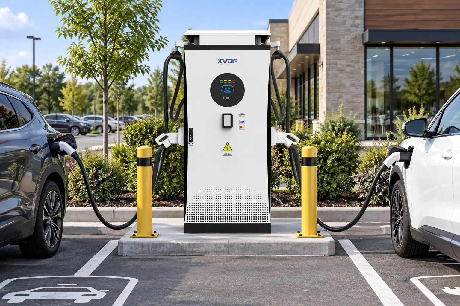
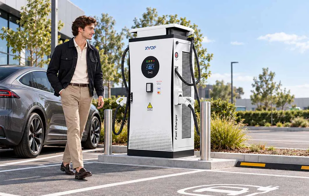
XYDF (Xinya EE) can be considered as one configurable source during this process, particularly when a buyer needs coordinated charger, cabinet and documentation discussions. Keep the evaluation evidence-led: compare the proposed configuration, test scope, service network and lead-time assumptions with other compliant bids. Review the company’s commercial DC fast charger range and products overview only after the duty cycle and grid envelope are documented. This sequence keeps how to choose a dc fast charger anchored to site evidence and buyer risk, while a commercial DC EV charger is judged on delivered service rather than peak output.
Frequently asked questions
How do I know whether 60 kW or 120 kW is right for my depot?
Estimate energy required per vehicle, available dwell and how many vehicles overlap. If a vehicle can remain parked for two hours, 60 kW may meet the duty cycle; if departures cluster within 45 minutes, 120 kW or managed sharing may be needed. Validate with telematics and a load simulation rather than nameplate power alone.
Does an 800 V charger charge every EV faster?
No. The vehicle, battery temperature, SoC and cable current limit determine delivered power. An 800 V-capable vehicle can reduce current for a given kW, but a 400 V vehicle may receive a lower output from the same cabinet. Test representative models and read the charging curve.
What transformer size is needed for a 480 kW charger?
There is no universal answer. Include charger efficiency, auxiliary loads, power factor, diversity, future expansion and the EMS import cap, then confirm utility requirements and protection studies. An illustrative 480 kW output could require more than 480 kVA at the transformer because of losses and headroom; use the supplier’s declared input data.
Is liquid cooling always better than air cooling?
Liquid cooling is useful for high-current cables, compact dispensers and short dwell, but it adds pumps, coolant and leak-detection maintenance. Air cooling may be simpler and adequate at lower power or moderate climate. Compare derating curves, noise, service intervals and total cost for the actual site.
Which communication standard should a CPO specify?
Specify the OCPP version and smart-charging features your backend supports; add ISO 15118 only when target vehicles, certificates and the backend are ready. Confirm offline operation, transaction records, firmware management and cybersecurity responsibilities. Interoperability testing with your exact platform is more informative than a protocol logo.
How should uptime be written in a charger contract?
Define availability by connector, measurement interval, planned-maintenance windows and exclusions such as utility outages or vandalism. Require event logs, response and restoration times, spare-part commitments and a reporting method. A percentage without these definitions cannot be compared across bids.
Authoritative references
- International Energy Agency, Global EV Outlook 2024.
- IEC 61851-1, Electric vehicle conductive charging system—General requirements.
- IEC 62196 series, Plugs, socket-outlets, vehicle connectors and vehicle inlets.
- ISO 15118-2, Road vehicles—Vehicle to grid communication interface.
- Open Charge Alliance, OCPP 2.0.1.
Closing principle: The best charger is the one whose delivered energy, grid behavior, service process and compliance evidence remain predictable after the opening-day peak has passed. If you are planning a new site or upgrading an existing one, use the duty-cycle and acceptance sequence above, then contact XYDF to discuss a configuration that fits your documented electrical and operational envelope.