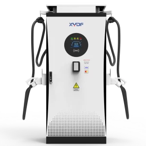
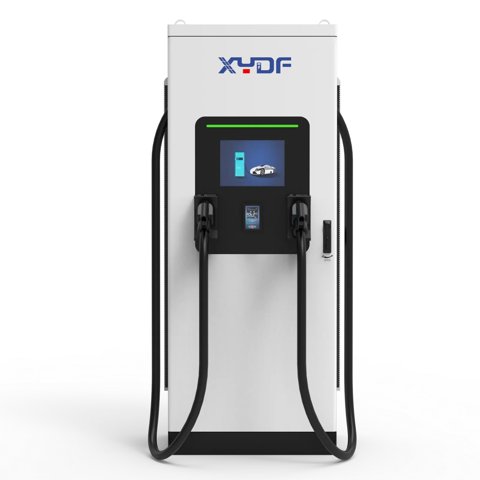
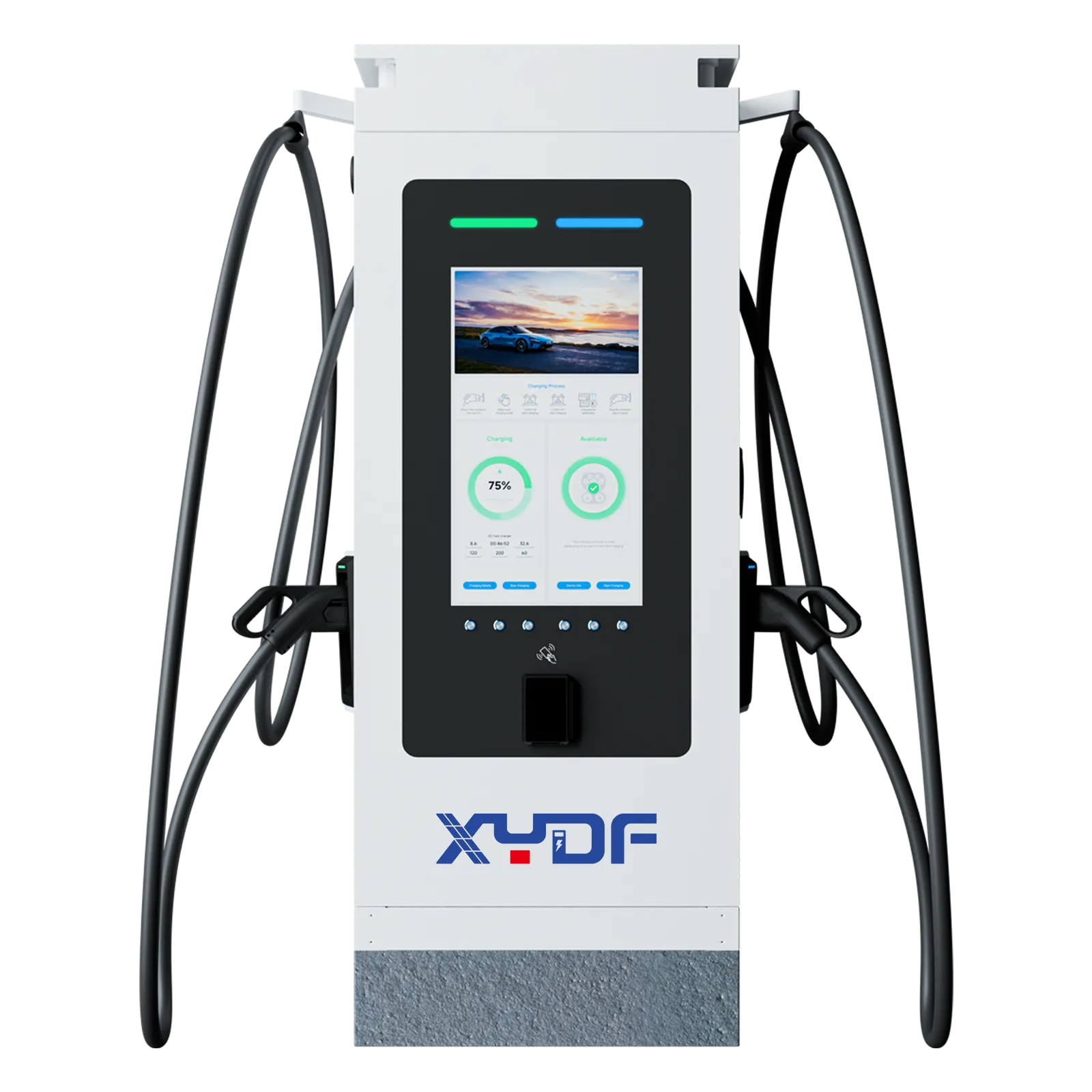
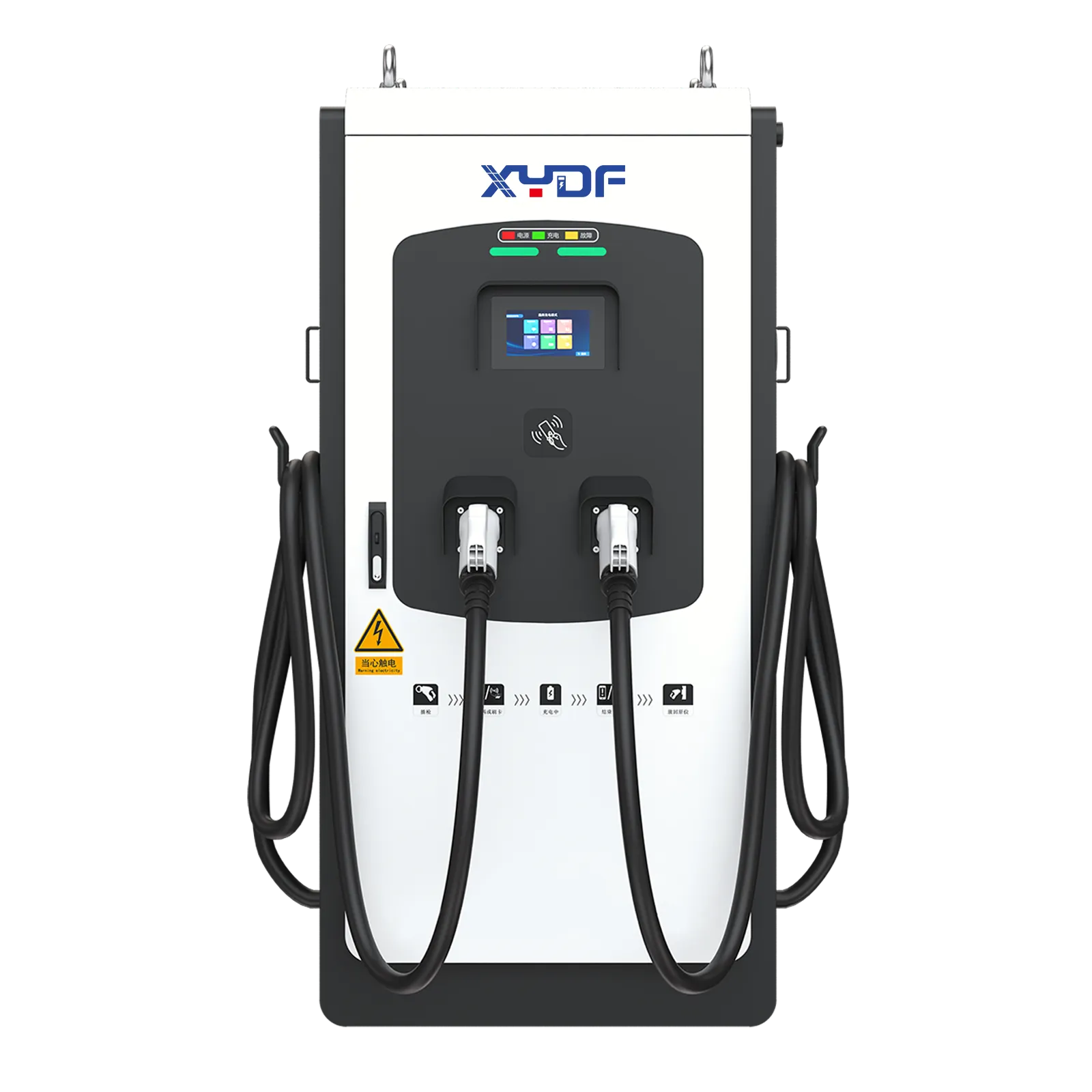
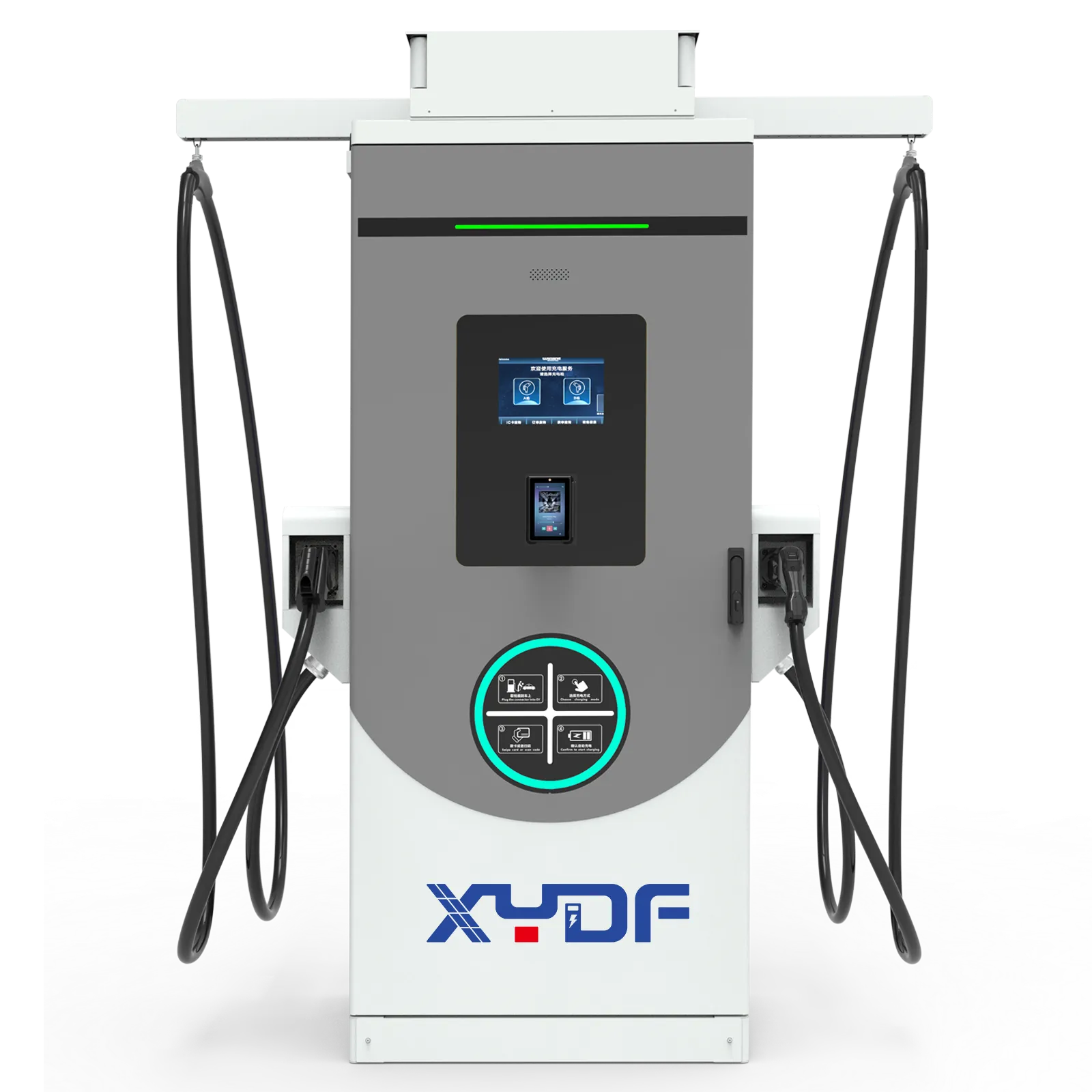
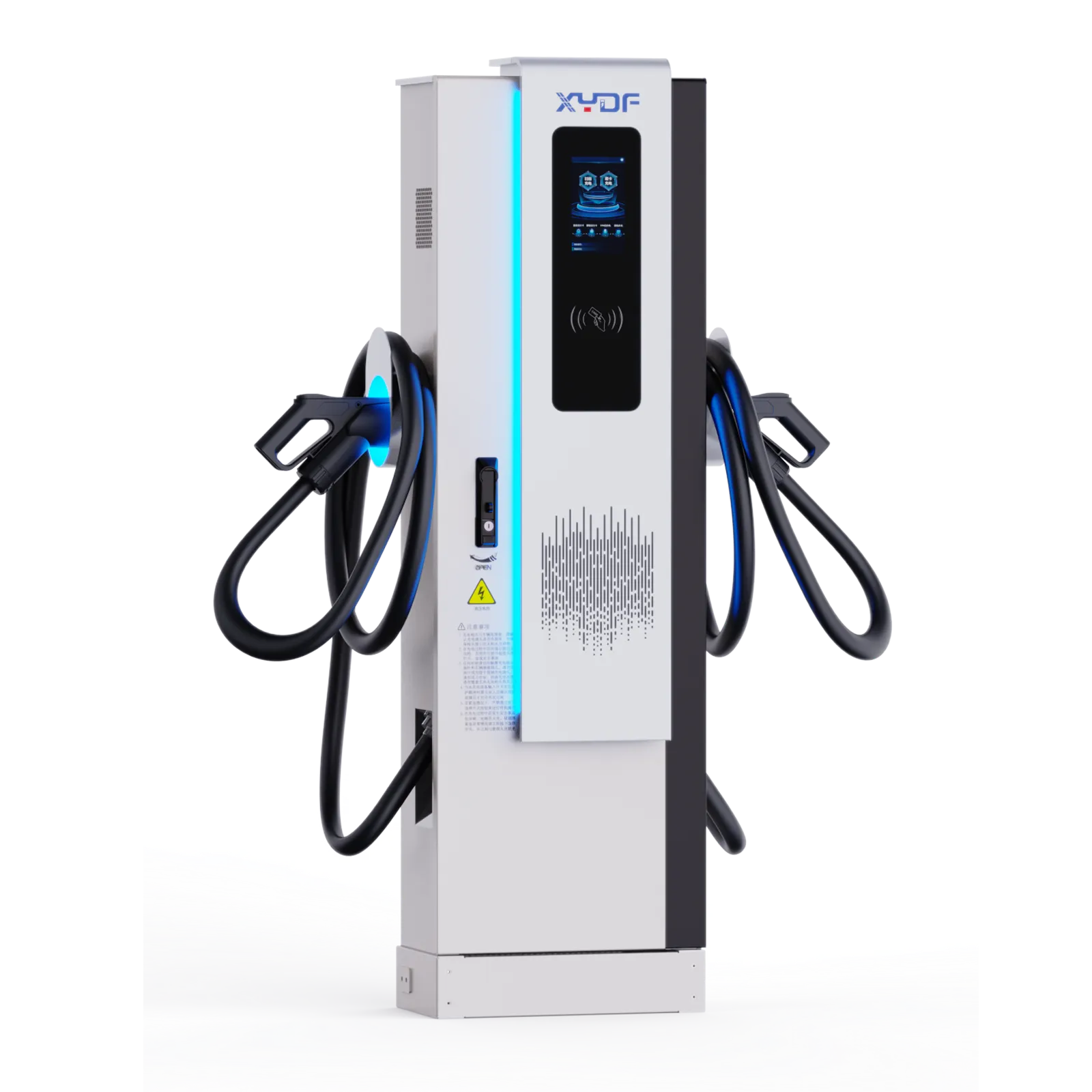
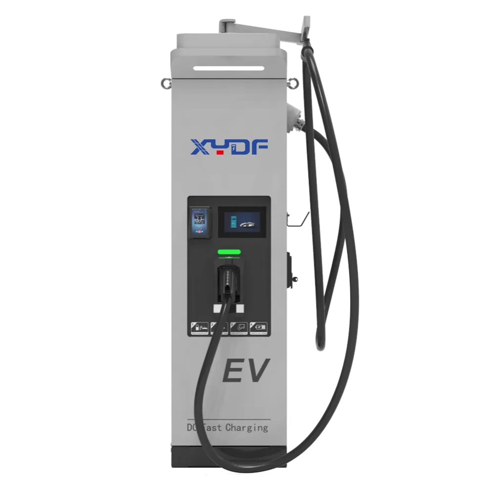
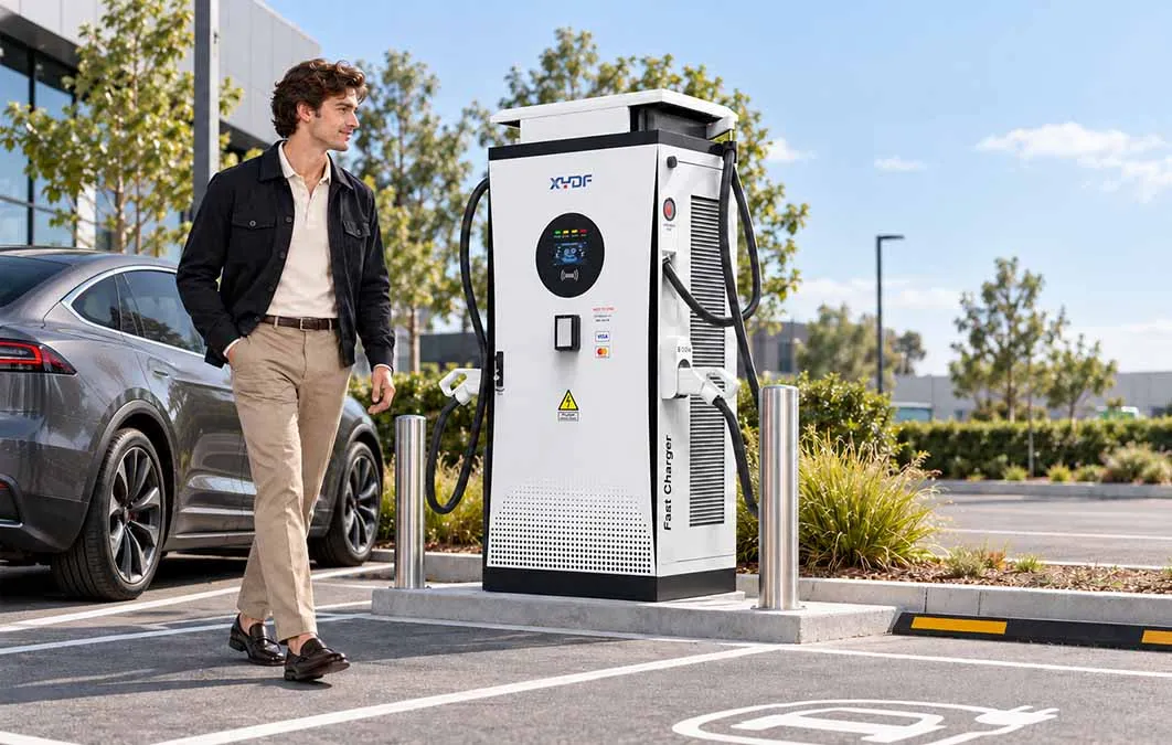
A highway rest area looks quiet until two coaches arrive together. Drivers expect a short stop, the operator needs stable demand, and the utility connection must remain within limits. A modern 350 kW DC fast charger coordinates power conversion, vehicle communication, cooling, and protection as one system.
A 350 kW DC Fast Charger is a high-power DC supply, not a larger AC wallbox. It rectifies grid power, controls voltage and current in real time, and follows the vehicle battery-management system. Safe deployment depends on cabinet architecture, liquid-cooled cables, site capacity, OCPP connectivity, and disciplined commissioning.
Vehicle compatibility is a measured interface question. Confirm connector and communication requirements, voltage and current ranges, battery state-of-charge behaviour, thermal limits, cable reach, and simultaneous-use rules for the intended vehicles. A charger rated for a high peak does not guarantee that every vehicle will accept that power or maintain it through the session. For the public planning context, see ISO 15118 road vehicles communication standard; the site-specific acceptance record still controls the final decision.
Three-phase AC passes through rectifiers and a DC bus. Parallel power modules let the controller ramp smoothly, isolate a failed module, and maintain efficiency across changing loads. The dispenser verifies connector locking, insulation, voltage, and battery limits before closing its contactors. The car continuously reports requested current, state of charge, and temperature.
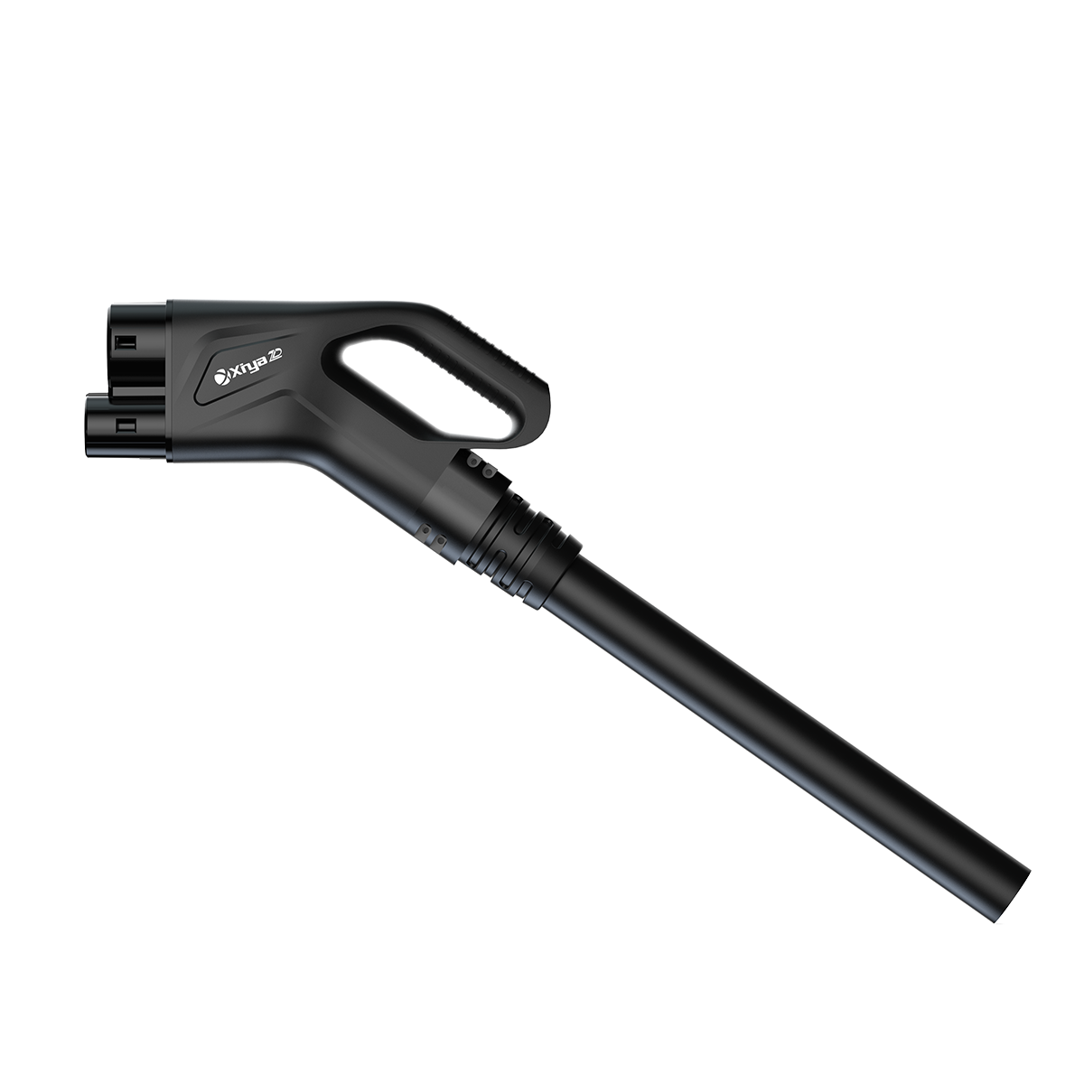
At 350 kW, a 400–1000 V vehicle may draw hundreds of amperes. A liquid-cooled cable, temperature sensing and connector checks are part of the current path; the exact current and taper still follow the vehicle and battery-management limits. A DC Fast Charger therefore needs liquid-cooled cables, temperature sensors, insulation monitoring, emergency stop circuits, and arc-resistant contactors. High-speed digital communications coordinate the charger and BMS several times per second; the charger never forces a fixed current into the pack.
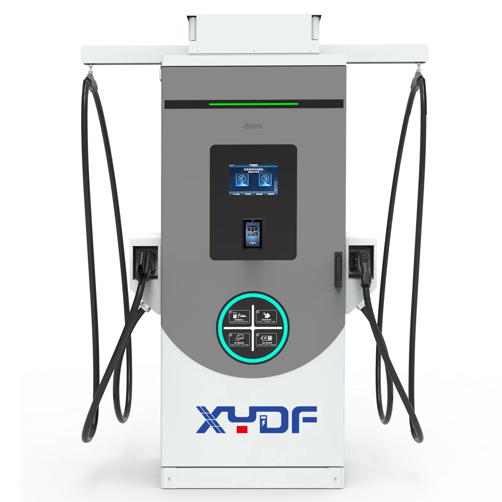
DOE explains that extreme fast charging can reach up to 350 kW, but high battery power produces heat and the vehicle’s power electronics may not accept the full rate. The procurement question is therefore energy delivered within the planned dwell time, not a promise that every vehicle will draw 350 kW.
| Factor | Effect | Design response |
|---|---|---|
| Vehicle voltage and BMS limit | Sets accepted current | Match voltage range and control curve |
| State of charge | Power tapers as the pack fills | Plan energy, not peak kW alone |
| Thermal conditions | Heat can reduce current | Use active cooling and sensors |
| Grid capacity | Limits simultaneous output | Add power sharing or storage |
For a high-power site plan, record the utility limit, simultaneous-output assumption, thermal derating curve, emergency isolation location and maintenance clearances before approving the equipment schedule.
Start with fault-current calculations, switchgear, earthing, surge protection, cable routing, bollards, drainage, and an accessible emergency isolation point. Specify equipment for salt, dust, rain, and low temperatures. IEC 61851 and regional electrical codes define conductive charging behavior; CCS or the selected connector standard defines the vehicle interface.
For networked operation, request OCPP support and signed firmware updates. A hyper charging station should log alarms, insulation faults, connector temperatures, and energy delivered. Remote diagnostics reduce downtime, while cybersecurity requires unique credentials, least-privilege access, encrypted transport, and a recovery plan.
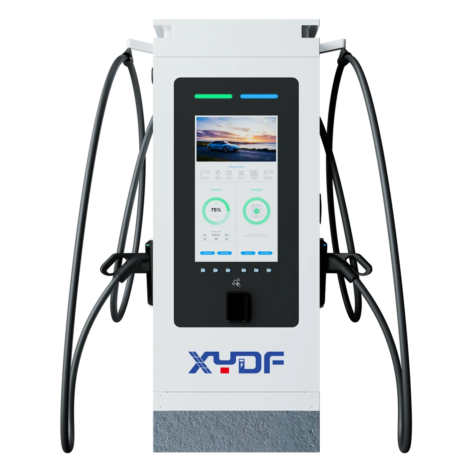
Compare utilization, tariffs, demand charges, and service revenue. A 350 kW unit can shorten dwell time, but a 120–240 kW configuration may perform better at a constrained site. Consider a modular DC fast charging platform that can add modules later. On-site storage can shave peaks and reduce the grid upgrade.
Measure queue time, sessions per day, delivered kWh, and uptime. A well-positioned DC Fast Charger earns more from the same bay when software routes vehicles to the right connector and schedules fleet departures.
Collect connector and communication requirements, battery voltage range, maximum accepted current and power, charge-curve behaviour by state of charge and temperature, usable energy target, cable reach, and simultaneous-use constraints. Use representative vehicles in acceptance testing; the charger nameplate alone cannot establish compatibility or charging time.
Yes. It is a high-power level 3 charging station, although actual vehicle power may be lower because of voltage and tapering.
High capital cost, grid impact, and heat management are the main disadvantages.
Usually no. Follow the vehicle maker guidance; many drivers use an 80% target for daily use.
Common systems cover roughly 200–1000 V DC and follow the vehicle request.
For adjacent planning topics, read our AC overnight charging guide and solar EV charging design guide. XYDF can compare a DC Fast Charger platform for your site. Contact our engineering team.
 Xinya Dongfang Electricity Technology Co., Ltd.